Novel oil tanker flue gas inert system detection device and method

A detection device and flue gas technology, which is applied in the direction of measuring device, lubrication indicator device, heat measurement, etc., can solve the problem of inaccurate data monitoring and other problems

Active Publication Date: 2021-05-18
ZHEJIANG OCEAN UNIV
View PDF5 Cites 0 Cited by
  • Summary
  • Abstract
  • Description
  • Claims
  • Application Information

AI Technical Summary

Problems solved by technology

[0005] The purpose of the present invention is to provide a novel oil tanker flue gas inert system detection device and method, real-time monitoring of the input flue gas parameters, and rectification of the flue gas transported in the pipeline In or

Method used


Image

  • Novel oil tanker flue gas inert system detection device and method
  • Novel oil tanker flue gas inert system detection device and method
  • Novel oil tanker flue gas inert system detection device and method

Examples


Embodiment 1

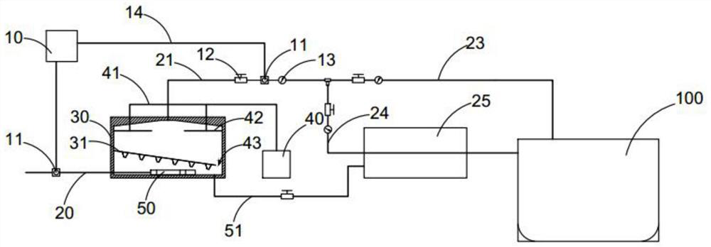
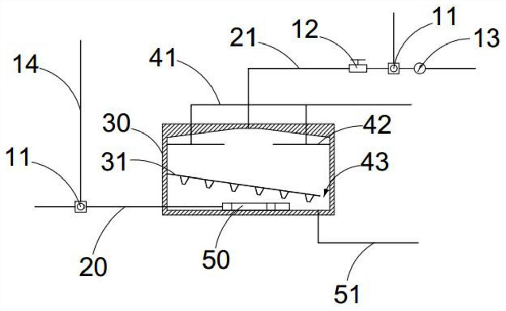
[0035] See attached Figure 1-6 As shown, a novel oil tanker flue gas inert system detection device and method, including:

[0036] The gas pipe body 20 is used to transport flue gas,

[0037] The flue gas purifier 30, the flue gas purifier 30 is provided with a spray pipe 42, the spray pipe 42 is connected with the water pump 40 arranged outside the flue gas purifier 30 through the first water pipe 41, the gas pipe body 20 is connected with the flue gas The purifier 30 communicates and sends the flue gas to the inner bottom of the flue gas purifier 30,

[0038] The first flue gas exhaust pipe 21, one end of the first flue gas exhaust pipe 21 communicates with the upper part of the flue gas purifier 30, and the other end is connected to a three-way pipe, one of which is connected to the second flue gas exhaust pipe 23, and the second flue gas The exhaust pipe 23 communicates with the ship's oil storage tank 100, and the other nozzle is connected to the third smoke exhaust pi...

Embodiment 2

[0053] The further optimization scheme of present embodiment on the basis of embodiment 1 is: see appendix Figure 7 , 8 As shown, a coaxial auxiliary rectifying element 80 is also provided in the rectifying sleeve body 70. The auxiliary rectifying element 80 includes a tapered ball bearing 81 connected to the inner wall of the rectifying sleeve body 70. The main disk body 85, the disk surface of the rotating main disk body 85 is respectively provided with a first through hole 82 and a third through hole 83 which are arranged around and through, and the middle part of the rotating main disk body 85 is connected with a rotatable rotating cylinder 84, and the rotating cylinder Rotating blades 86 are arranged on the cylinder side of 84, and the two ends of the rotating cylinder 84 can be respectively connected with the rotating main disk 85. In the present invention, the auxiliary rectifier 80 arranged inside the rectifying sleeve body 70 is used to realize the spiral trajectory...


PUM


Abstract

The invention discloses a novel oil tanker flue gas inert system detection device and method, and belongs to the technical field of oil tanker explosion prevention. The novel oil tanker flue gas inert system detection device comprises a gas delivery pipe body, a flue gas purifier and a first flue gas exhaust pipe, wherein the gas delivery pipe body is communicated with the flue gas purifier and is used for delivering flue gas to the inner bottom of the flue gas purifier, one end of the first flue gas exhaust pipe is communicated with the upper portion of the flue gas purifier, the other end of the first flue gas exhaust pipe is connected with a three-way pipe, one pipe opening is connected with a second flue gas exhaust pipe, the second flue gas exhaust pipe is communicated with a ship oil storage bin, the other pipe opening is connected with a third flue gas exhaust pipe, the third flue gas exhaust pipe is communicated with a ship oil storage bin, and a pipe body of the third flue gas exhaust pipe passes through a water tank with a built-in water body. The novel oil tanker flue gas inert system detection device can monitor input flue gas parameters in real time, rectify flue gas delivered in a pipeline to solve the problem of inaccurate data monitoring caused by turbulent flow and other factors, and meanwhile, can reasonably process the delivered flue gas to ensure normal use of the delivered flue gas in the ship oil storage bin.

Description

technical field [0001] The invention belongs to the technical field of explosion protection for oil tankers, and in particular relates to a novel oil tanker flue gas inert system detection device and method. Background technique [0002] The descriptions in this section merely provide background information related to the disclosure in this application and may not constitute prior art. [0003] In recent years, with the rapid development of the economy, countries around the world have increasingly strong demand for energy, the trade between oil importing countries and exporting countries has gradually expanded, and the transportation capacity and volume of oil tankers have increased rapidly. The resulting oil tanker transportation safety and The problem of preventing marine pollution is also becoming more complex. As we all know, fire source, combustible gas and oxygen are the three major elements that cause an explosion. If any of them can be eliminated, the explosion will...

Claims


Application Information

Patent Timeline
IPC IPC(8): G01N33/00G01K13/024G01F23/00
CPCG01N33/0036G01K13/02G01F23/00
Inventor 王帅军高雅婷林嘉斌朱姗姗干鑫华夏孟胜林祥伟
Owner ZHEJIANG OCEAN UNIV
Why Eureka
Try Eureka