Intelligent dewaxing and dewatering purification device

A technology for dewaxing and water removal and purification equipment, which is applied in chemical instruments and methods, chemical/physical processes, chemical/physical/physicochemical processes, etc. It can solve the problem of zirconium sand falling off and mixed in wax, and the water removal effect is not good , water mixed in, etc., to achieve the effects of reducing heat loss, improving water removal efficiency, and improving water purification efficiency

Inactive Publication Date: 2021-05-21
王政清
View PDF1 Cites 4 Cited by
  • Summary
  • Abstract
  • Description
  • Claims
  • Application Information

AI Technical Summary

Problems solved by technology

[0002] At present, in the investment casting industry, wax needs to be recycled many times. The investment casting first needs to make a wax mold, and then make a mold shell. After the mold shell is dried, put the mold shell in a dewaxing reaction kettle to pass water The wax is removed from the mold shell, and the steam guide valve is always open during the whole dewaxing process, so that a large amount of condensed water will be produced to merge with the wax, and the zirconium sand on the mold shell will fall off and be mixed with the wax. If it is reused , the water and other impurities in the wax must be separated; the commonly used method is steam heating, but it is easy to mix water into it when steam heating
[0003] After retrieval, Chinese Patent No. CN 206276869 U discloses an intelligent dewaxing and dewatering purification device, including a boiler, which is provided with a dewaxing reactor, a dehydration reactor and a compressed air heating tube, the dewaxing reactor and There is a wax pipe connected between the water removal reactors, and the output end of the compressed air heating pipe is connected to the dewaxing reactor; however, this device has the following disadvantages: not enough energy saving, and the water removal effect is not good. Dewaxing and water purification device to solve such problems

Method used


Image

  • Intelligent dewaxing and dewatering purification device
  • Intelligent dewaxing and dewatering purification device
  • Intelligent dewaxing and dewatering purification device

Examples


Embodiment Construction

[0021] The following will clearly and completely describe the technical solutions in the embodiments of the present invention with reference to the accompanying drawings in the embodiments of the present invention. Obviously, the described embodiments are only some, not all, embodiments of the present invention.

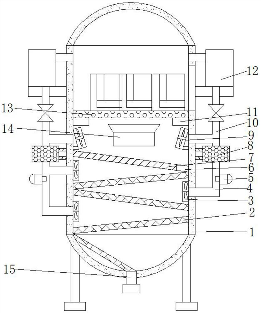
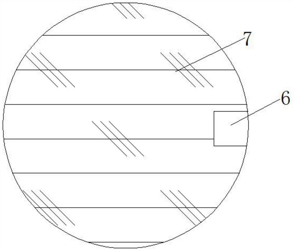
[0022] refer to Figure 1-3 , an intelligent dewaxing and dewatering purification device, comprising a reactor body 1, a mesh plate 13 arranged horizontally is welded on the inner wall of the reactor body 1, and protective plates 11 distributed equidistantly are welded on the bottom end of the mesh plate 13, and the reaction kettle The second fan 9 equidistantly distributed is welded on the inner wall of the body 1, and two steam heaters 14 are welded on the inner wall of the reactor body 1, and the height of the top of the steam heater 14 is greater than the height of the top of the second fan 9. The inner wall of the main body 1 is welded with a deflector 7 placed ...


PUM


Abstract

The invention discloses an intelligent dewaxing and dewatering purification device which comprises a reaction kettle body, a horizontally-arranged net plate is welded to the inner wall of the reaction kettle body, protection plates distributed at equal intervals are welded to the bottom end of the net plate, and second fans distributed at equal intervals are welded to the inner wall of the reaction kettle body. Two steam heaters are welded to the inner wall of the reaction kettle body, the height of the top ends of the steam heaters is larger than that of the top end of the second fan, an obliquely-arranged flow guide plate is welded to the inner wall of the reaction kettle body, a flow guide hole is formed in one side of the outer wall of the top of the flow guide plate, and the flow guide plate is located at the bottom of the second fan. Flow guide pipes which are distributed in a zigzag manner are welded on the inner wall of the reaction kettle body. According to the invention, wax can be fully heated, so that water in the wax is fully evaporated, the water removal efficiency is improved, hot air in the reaction kettle body can be recycled, heat loss is reduced, and the device is energy-saving, environment-friendly and high in intelligent degree.

Description

technical field [0001] The invention relates to the technical field of dewaxing, in particular to an intelligent dewaxing water removal and purification device. Background technique [0002] At present, in the investment casting industry, wax needs to be recycled many times. The investment casting first needs to make a wax mold, and then make a mold shell. After the mold shell is dried, put the mold shell in a dewaxing reaction kettle to pass water The wax is removed from the mold shell, and the steam guide valve is always open during the whole dewaxing process, so that a large amount of condensed water will be produced to merge with the wax, and the zirconium sand on the mold shell will fall off and be mixed with the wax. If it is reused , the moisture and other impurities in the wax must be separated; the commonly used method is steam heating, but it is easy to mix water into it when steam heating. [0003] After retrieval, Chinese Patent No. CN 206276869 U discloses an i...

Claims


Application Information

Patent Timeline
Patent Type & Authority Applications(China)
IPC IPC(8): B01J19/00B01J19/24B22C7/02B01D1/00B01D1/30B01D53/26
CPCB01D1/0041B01D1/30B01D53/26B01D53/261B01J19/0053B01J19/24B22C7/02
Inventor 王政清
Owner 王政清
Why Eureka
Try Eureka