High-throughput cavitation and electrocoagulation apparatus

a cavitation and high-throughput technology, applied in the direction of crystal growth process, polycrystalline material growth, separation process, etc., can solve the problems of high power consumption, inability to efficiently use continuous processing, and inability to achieve continuous processing. , to achieve the effect of high rate and efficient purification of water

Active Publication Date: 2014-03-18
CAVITATION TECH
View PDF29 Cites 7 Cited by
  • Summary
  • Abstract
  • Description
  • Claims
  • Application Information

AI Technical Summary

Benefits of technology

[0021]To provide a method that provides a high-throughput combined with a high efficiency of water purification.
[0022]To provide a method that does not require periodic shutdown of the unit for electrode surface cleaning.
[0023]To provide a method that allows simultaneous action of hydrodynamic cavitation, electrolysis and in situ coagulation to bring about a synergistic effect that results in a highly efficient purification.
[0024]To provide a compact apparatus, in which cavitation deactivates harmful microorganisms, creates vigorous mixing conditions and facilitates destruction and oxidation of contaminants by the electrocoagulation-generated active species.

Problems solved by technology

In practice, power consumption is higher due to heating water, electrode polarization, oxide film formation and other processes.
Acoustic cavitation requires a batch environment and cannot be used efficiently in continuous processing, because energy density and residence time would be insufficient for a high-throughput.
In addition, the effect of acoustic cavitation diminishes with an increase in distance from the radiation source.
The known methods of water purification that employ both electrocoagulation and cavitation use them in a periodic manner, which reduces the process output, and requires using rather complex equipment.

Method used


Image

  • High-throughput cavitation and electrocoagulation apparatus
  • High-throughput cavitation and electrocoagulation apparatus
  • High-throughput cavitation and electrocoagulation apparatus

Examples


Embodiment Construction

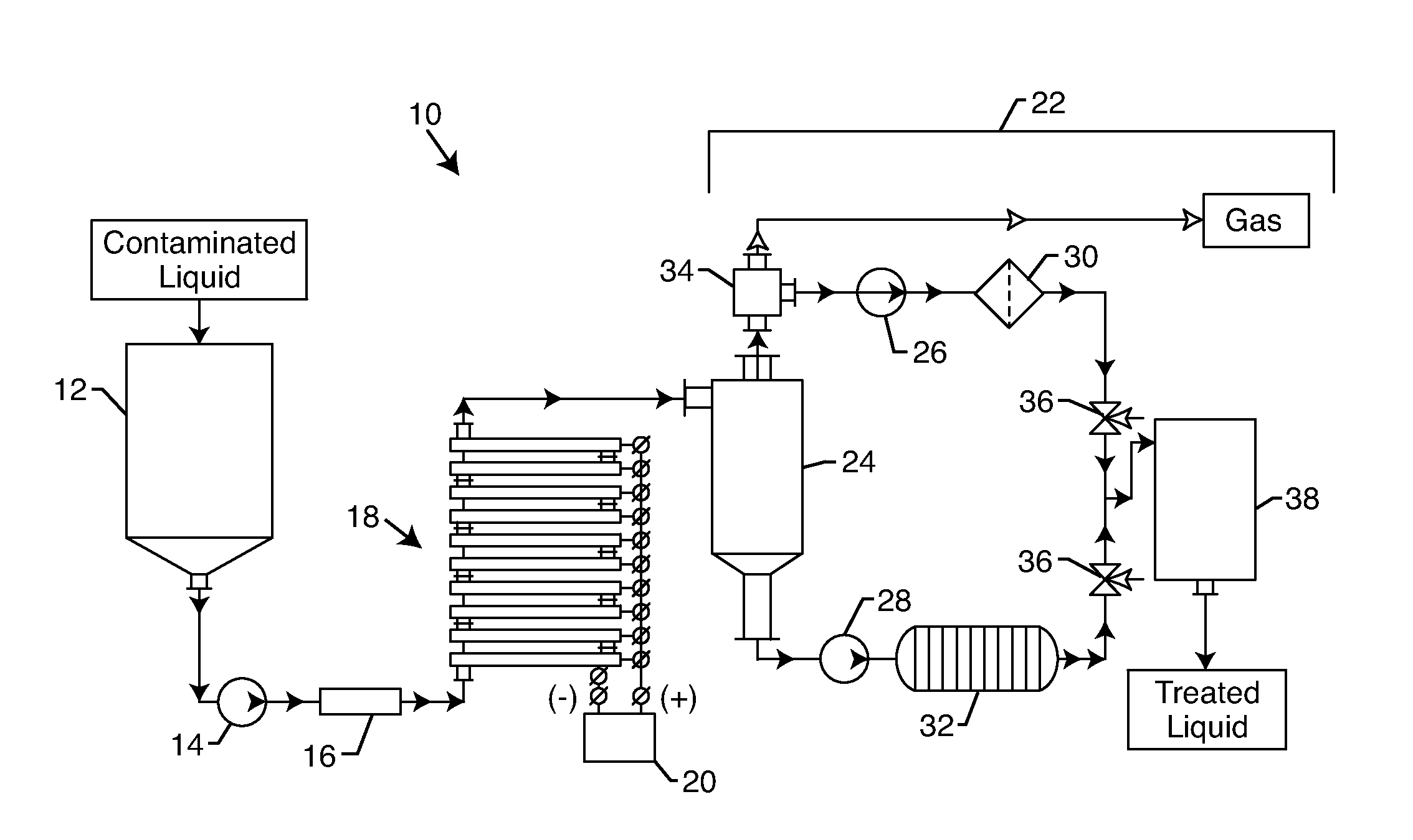
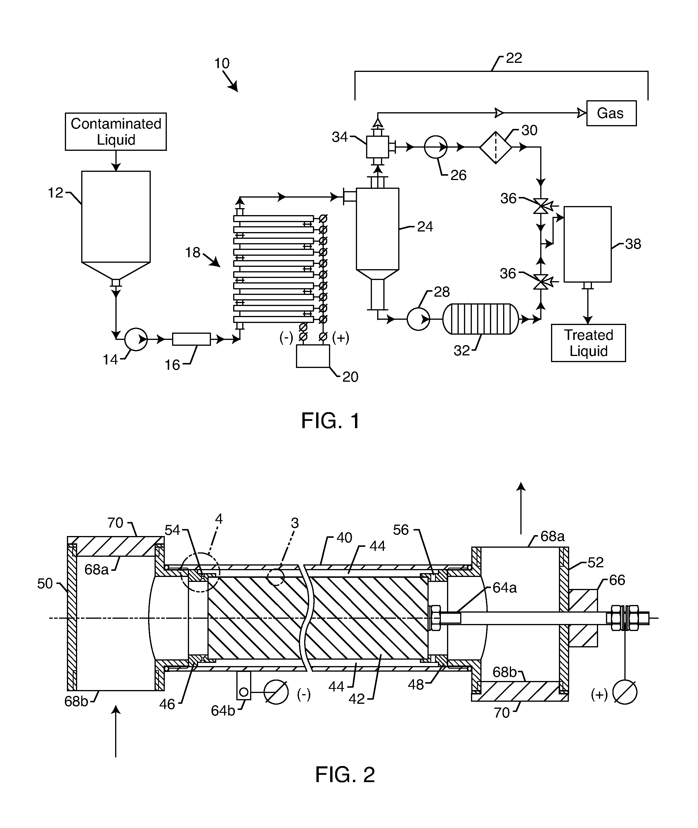
[0040]A principal diagram of a possible high-throughput cavitation electrocoagulation system 10 is depicted in FIG. 1. The system 10 is comprised of the several parts that make it possible to efficiently treat contaminated water and remove various contaminants therefrom by using electrocoagulation simultaneously with flow-through hydrodynamic cavitation. The system 10 consists of inlet tank 12, which is filled with fluid to be purified. A high-pressure pump 14 feeds the fluid to a pre-cavitation-generating unit 16 for the cavitation pre-treatment of the fluid. A set of the inventive high-throughput cavitation and electrocoagulation reactors 18 provide the simultaneous application of hydrodynamic cavitation and an electric field, to impose electrochemical, heat and mechanical action on the fluid to be purified. A controlled electrical source with DC output 20 is connected to the reactor 18. A separation system 22 for removal of solid and gaseous flock and debris from the fluid to be ...


PUM

PropertyMeasurementUnit
temperatureaaaaaaaaaa
angleaaaaaaaaaa
angleaaaaaaaaaa

Abstract

The invention relates to a cavitation and electrocoagulation reactor comprising a hollow cylindrical cathode having a cylindrical anode coaxially disposed therein to form an annular interelectrode gap between the contact surfaces. An inlet sleeve and an outlet sleeve disposed in the respective inlet and outlet of the cathode and abutting against opposite ends of the anode seal the interelectrode gap from the respective inlet and outlet of the cathode. A set of channels disposed in the wall of the inlet sleeve connect the inlet to the interelectrode gap. Similarly, a set of openings disposed in the outlet sleeve connect the interelectrode gap to the cathode outlet. An electrical source has first and second terminals respectively connected to the anode and the cathode. The method for removing contaminants from a contaminated fluid flow involves the simultaneous application of hydrodynamic cavitation and electrocoagulation to the contaminated fluid flow.

Description

BACKGROUND OF THE INVENTION[0001]The invention relates to an apparatus and method of purification and treatment of potable water, ground water, industrial water, sewage water, etc. and finds numerous applications in drinking water production, food, chemical, oil, energy, wood, pulp and paper industries, mining and metal-processing and similar industries. Removable contaminants include metals, petroleum products, colloidal particles, living species, organics, dyes, polymers, surface-active compounds and other matter whose concentration can be decreased to the allowable levels in one pass through the present apparatus. The proposed water treatment method and the device generate changes in the fluidic flow's velocity, pressure, temperature, voltage, resistance and chemical composition and physical properties in order to reduce the concentration of impurities. The simultaneous action of hydrodynamic cavitation, electrocoagulation and the coagulants and active chemical species formed in ...

Claims


Application Information

Patent Timeline
Patent Type & Authority Patents(United States)
IPC IPC(8): C02F1/46
CPCC02F2201/4611C02F2201/003C02F2201/4617C02F2001/46152C02F2201/46175C02F1/34C02F2103/08C02F1/463C02F2001/46138
Inventor GORDON, ROMANGORODNITSKY, IGORPROMTOV, MAXIM A.
Owner CAVITATION TECH
Why Eureka
Try Eureka