Liquid pumping system of piston type slurry pump with circulating cleaning device

A cleaning device, a piston-type technology, which is applied to the components of the pumping device for elastic fluids, the variable-capacity pump components, the pump, etc., can solve the problem that the mud pump cannot adapt to the large pump pressure, Insufficient liquid output, difficult piston replacement, etc., to achieve the effect of good piston sealing, easy disassembly, and reduced wear

Inactive Publication Date: 2021-05-25
SHANDONG ZHONGTAN MACHINERY
View PDF0 Cites 2 Cited by
  • Summary
  • Abstract
  • Description
  • Claims
  • Application Information

AI Technical Summary

Problems solved by technology

[0004] The purpose of the present invention is to provide a pumping system of a piston mud pump equipped with a circulating cleaning device, so as to solve the difficulties in replacing the piston and the sudden change of the working environment of the mud pump when a large pump pressure is required for a short time. The problem of adaptation, and when the medium contains sand with a large particle size, the amount of liquid entering and exiting is insufficient, and the wear of the piston rod

Method used


Image

  • Liquid pumping system of piston type slurry pump with circulating cleaning device
  • Liquid pumping system of piston type slurry pump with circulating cleaning device
  • Liquid pumping system of piston type slurry pump with circulating cleaning device

Examples


Embodiment 1

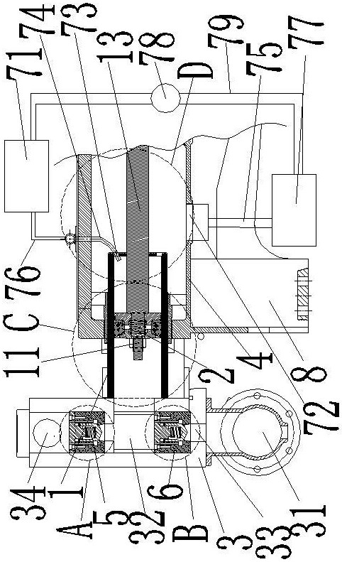
[0053] Example 1. Such as Figure 1-7 As shown, a pumping system of a piston mud pump with a circulating cleaning device is characterized in that it includes a piston rod, a piston 2, a piston tube 1, a valve box body 3, a piston tube installation tube 4, and a liquid inlet tube 31. Cleaning and lubricating device, pump body 8; the piston rod includes the left end part 11 of the piston rod and the body 13 of the piston rod arranged coaxially in the transverse direction.

[0054] The piston tube installation pipe 4 is horizontally arranged on the pump body 8, the left end of the piston tube installation pipe 4 is provided with a piston tube installation pipe end cover 41, and the centroid of the piston tube installation pipe end cover 41 is horizontally equipped with a piston tube 1, the piston tube 1 is installed with a piston 2, and the piston 2 is set on the left end part 11 of the piston rod; the right end of the piston tube 1 is provided with a piston tube end cap 12;

...

Embodiment 2

[0079] Example 2. Such as Figure 8-11 The difference between the present embodiment shown and Embodiment 1 is that: the radial outer peripheral surface of the piston tube fixing sleeve 42 is not provided with a left locking nut 43 on the left side of the piston tube mounting tube end cover 41; the water pump 7 is arranged on the Piston tube installation tube 4 outside. The piston tube 1 includes a steel piston tube body 14 and a wear-resistant sleeve 15 arranged on the radially inner peripheral surface of the piston tube body 14 . The lock nut 43 is screwed to the radially outer peripheral surface of the piston tube body 14 .


PUM


Abstract

The invention discloses a liquid pumping system of a piston type slurry pump with a circulating cleaning device. The liquid pumping system comprises a piston rod, a piston, a piston pipe, a valve box body, a piston pipe mounting pipe, a liquid inlet pipe, a cleaning and lubricating device and a pump body; the piston rod comprises a piston rod left end part and a piston rod body which are transversely and coaxially arranged; the cleaning and lubricating device comprises a water suction pump; the water suction pump is arranged on the piston pipe mounting pipe or outside the piston pipe mounting pipe; a water tank and a sand settling box are arranged outside the piston pipe mounting pipe. According to the liquid pumping system of the piston type slurry pump with the circulating cleaning device, when the sand content in slurry is high and high pressure exists, liquid feeding and liquid discharging are smooth, the piston can also be automatically adjusted, the cleaning and lubricating device is adopted, the large-diameter slurry particles can be effectively prevented from being accumulated on the surface of the plunger, and the problem of sealing failure caused by frequent movement is solved.

Description

technical field [0001] The invention relates to the technical field of mud pumps, in particular to a pumping system of a piston mud pump provided with a circulation cleaning device. Background technique [0002] Mud pump is a very important production equipment in the oil field industry and an important part of drilling equipment. It is mainly used for deep well and shallow well operations in oil fields. It can complete water blocking and oil displacement operations to oil wells, and can also be used for cement plugging during oil field workover. , channel sealing, well washing, sand washing and cementing operations, near and long-distance transportation of crude oil and pressure testing, etc. [0003] The piston of the existing mud pump The piston of the mud pump is made of metal materials and wear-resistant materials. Since the piston needs to move repeatedly and bear a certain high pressure, the piston has high requirements for machining accuracy. Because the piston need...

Claims


Application Information

Patent Timeline
Patent Type & Authority Applications(China)
IPC IPC(8): F04B15/02F04B53/00F04B53/02F04B53/10F04B53/14F04B53/22F04B53/18
CPCF04B15/02F04B53/00F04B53/02F04B53/10F04B53/14F04B53/143F04B53/18F04B53/22
Inventor 李洪平李鲁杰张梅
Owner SHANDONG ZHONGTAN MACHINERY
Why Eureka
Try Eureka