Mixed gas supply type visual natural gas hydrate experiment system

An experimental system, hydrate technology, applied in the field of mixed gas supply visual natural gas hydrate experimental system, can solve the problems of low level of automation and digitalization, single input gas composition, lack of visualization, etc., to achieve easy sampling and easy operation , digitalization and high level of automation

Inactive Publication Date: 2021-05-25
SOUTHWEST PETROLEUM UNIV
View PDF8 Cites 5 Cited by
  • Summary
  • Abstract
  • Description
  • Claims
  • Application Information

AI Technical Summary

Problems solved by technology

Although there are a variety of natural gas hydrate experimental systems, with the deepening of academic research, the existing systems can no longer meet the needs of scientific research, and there are problems such as single input gas components, lack of visualization, and difficult sampling of gas or liquid experimental materials. , and the level of automation and digitalization is low, and the manipulation of experimental equipment and data recording are quite cumbersome

Method used


Image

  • Mixed gas supply type visual natural gas hydrate experiment system
  • Mixed gas supply type visual natural gas hydrate experiment system

Examples


Embodiment 1

[0025] Embodiment 1: The structure and function implementation plan of each unit of the system

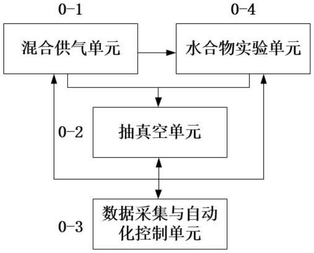
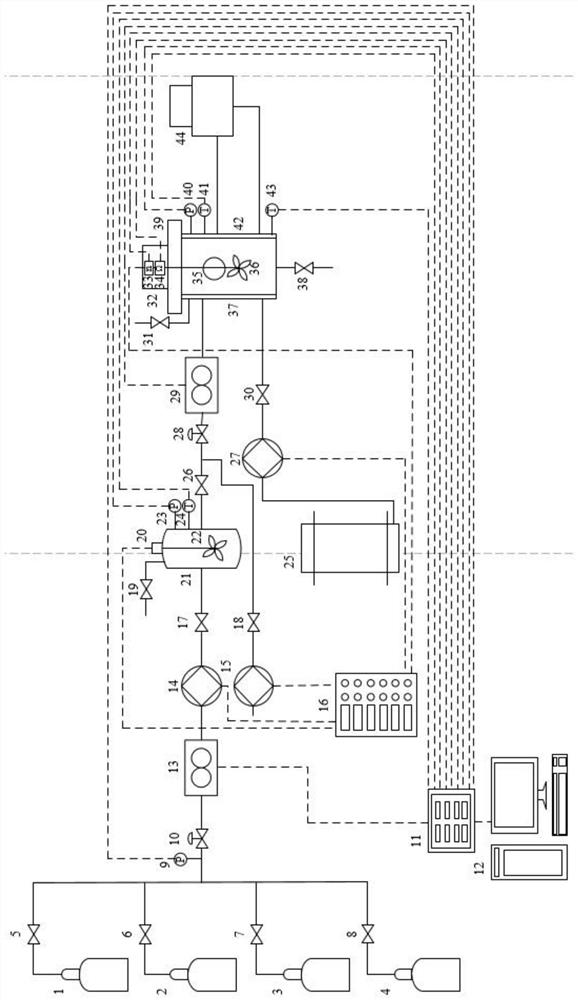
[0026] Such as figure 1 and figure 2 As shown, a mixed gas supply visual natural gas hydrate experimental system of the present invention can be divided into mixed gas supply unit 0-1, vacuum unit 0-2, data acquisition and automatic control unit 0-3, and hydrate experimental unit 0-4. The mixed gas supply unit 0-1 is connected with the hydrate experimental unit 0-4, and the high-pressure mixed gas is transmitted in one direction; the mixed gas supply unit 0-1, the hydrate experimental unit 0-4 are connected with the vacuum unit 0-2, and the one-way Air extraction; mixed gas supply unit 0-1, hydrate experiment unit 0-4, vacuum unit 0-2 are connected with data acquisition and automatic control unit 0-3, bidirectional transmission of electrical signals, instrument parameter acquisition and equipment control.

[0027] Mixed gas supply unit 0-1 includes methane gas cylinder 1, first...

Embodiment 2

[0031] Example 2: Basic Experimental Scheme for Methane Mixed Gas Hydrate Formation-Decomposition

[0032]Step 1: Operation of pipeline vacuum equipment before the experiment: Check the system connection and confirm whether all pipeline valves are closed when the equipment is not running. After confirmation, open the vacuum valve 18, the second intake valve 26, and the second pressure regulating valve 28, and simultaneously close the first intake valve 17, the first vent valve 19, the liquid inlet valve 30, the second vent valve 31, Drain valve 38 and reactor top cover 39. Then start the vacuum pump 15 through the control cabinet 16, observe the readings of the second pressure sensor 23 and the third pressure sensor 40, until the rated suction pressure of the vacuum pump 15 is reached and no white mist appears at the air outlet of the vacuum pump 15, then close the vacuum pump 15 and the vacuum valve 18. If the rated extraction pressure of the vacuum pump 15 cannot be reached...

Embodiment 3

[0053] Embodiment 3: High-pressure reactor vacuumizes operation separately

[0054] If the experiment needs to continue to use the remaining mixed gas from the previous experiment, the high pressure reactor 37 should be vacuumed separately. First check whether the second air intake valve 26, the second vent valve 31, the liquid discharge valve 38 and the top cover 39 of the reaction kettle are tightly closed, and after confirming that they are correct, open the vacuum valve 18 and the second pressure reducing valve 28, and start the vacuum pump 15 to start vacuuming Until the rated extraction pressure of the vacuum pump 15 is reached and white mist does not appear at the outlet of the vacuum pump 15, the vacuum pump 15, the vacuum valve 18 and the second pressure regulating valve 28 are closed, and the vacuuming operation of the high-pressure reactor is completed alone.


PUM


Abstract

The invention relates to a mixed gas supply type visual natural gas hydrate experiment system which mainly comprises a single-component gas cylinder, a data collector, a computer, a gas flowmeter, a gas booster pump, a vacuum pump, a control cabinet, a gas distribution tank, a liquid adding barrel, an injection pump, a high-pressure reaction kettle, a circulating water bath box, a pressure regulating valve, various sensors and pipeline matching valves. The system can be divided into a mixed gas supply unit, a vacuumizing unit, a data acquisition and automatic control unit and a hydrate experiment unit. The mixed gas supply unit is used for preparing multi-component high-pressure mixed gas; the vacuumizing unit is used for vacuumizing the system; the data acquisition and automatic control unit is used for monitoring parameters of each sensor in real time and remotely controlling the pump and the stirrer; the hydrate experiment unit is used for conducting hydrate experiments. According to the invention, the functions of multi-component gas input, hydrate generation visualization, gas or liquid experimental material sampling and the like can be realized, and various natural gas hydrate experiments can be carried out.

Description

technical field [0001] The invention relates to a mixed gas supply type visual natural gas hydrate experimental system, which belongs to the field of energy and chemical industry. Background technique [0002] Natural gas hydrate is a hot spot in the field of energy and chemical industry in recent years. On the one hand, deep-water natural gas hydrate has huge reserves and broad prospects for development. It is considered to be the main alternative energy source in the future. The field of gathering and transportation has been more and more widely used, and the natural gas hydrate generated under the condition of low temperature and high pressure has become a major problem hindering the normal transportation of pipelines, and it is necessary to prevent and control possible pipeline blockages. However, no matter the research on gas hydrate production, suppression or slurry transportation is based on the basic formation or decomposition mechanism of gas hydrate, it is very im...

Claims


Application Information

Patent Timeline
Patent Type & Authority Applications(China)
IPC IPC(8): G01N33/00
CPCG01N33/00
Inventor 敬加强张兴堂孙杰付斌石运亮王海燕杨航程原招郭雨莹
Owner SOUTHWEST PETROLEUM UNIV
Why Eureka
Try Eureka