
A magnetoelectric dipole antenna array based on 3D printing technology

A dipole antenna, 3D printing technology, applied in antenna arrays, antennas, circuits, etc., can solve the problems of error sensitivity, difficult processing, and excessive weight, and achieve stable gain, stable pattern, and rapid prototyping. Effect

Active Publication Date: 2022-03-29
SOUTH CHINA UNIV OF TECH
View PDF9 Cites 0 Cited by
  • Summary
  • Abstract
  • Description
  • Claims
  • Application Information

AI Technical Summary

Problems solved by technology

[0009] The invention provides a magnetoelectric dipole antenna array based on 3D printing technology, which is used to solve the complex structure, difficult processing, error sensitivity in post-processing, and weight caused by the introduction of metal structures in the prior art. Too heavy, difficult to integrate and other issues

Method used


Image

  • A magnetoelectric dipole antenna array based on 3D printing technology
  • A magnetoelectric dipole antenna array based on 3D printing technology
  • A magnetoelectric dipole antenna array based on 3D printing technology

Examples


Embodiment Construction

[0032] In order to better understand the present invention, the content of the present invention is further illustrated below in conjunction with the examples, but the content of the present invention is not limited to the following examples.

[0033] This embodiment provides a magnetoelectric dipole antenna array based on 3D printing technology. The array is realized by 3D printing a dielectric material and a thin layer of electroplated metal copper. The dielectric constant of the dielectric material used is 2.9, and the loss tangent is 0.01. In other embodiments, the dielectric material can be flexibly selected according to the actual situation. Since the density of the dielectric material is much smaller than that of metal, the present invention has obvious advantages in weight compared with the traditional pure metal magnetoelectric dipole antenna.

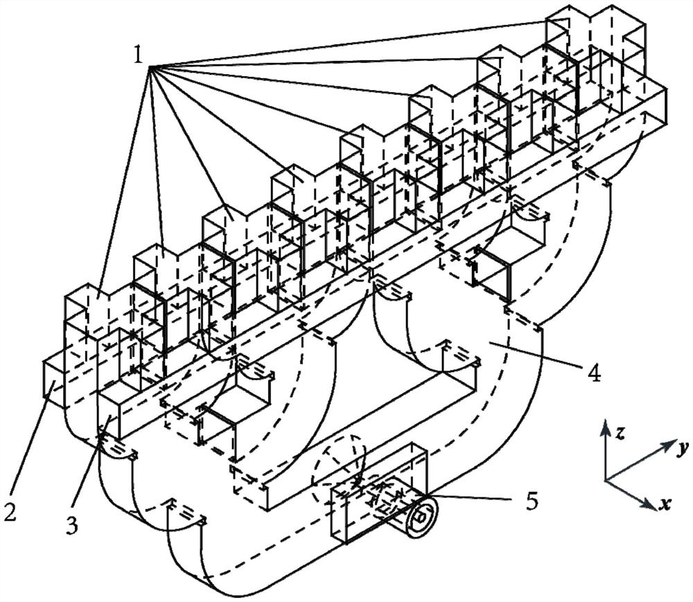
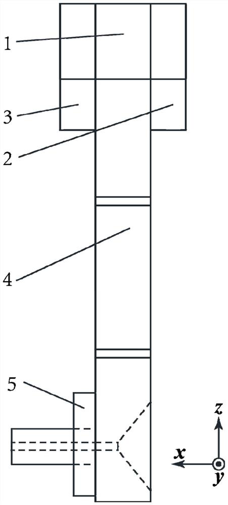
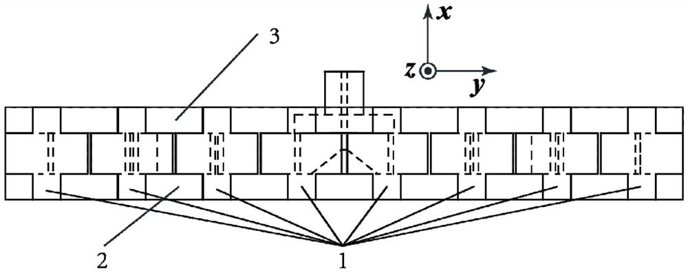
[0034] Such as figure 1 , figure 2 , image 3 As shown, the antenna array includes an integrally formed array body, a fi...


PUM


Abstract

A magnetoelectric dipole antenna array based on 3D printing technology provided by the present invention includes an array body, a first rectangular reflector, a second rectangular reflector and a coaxial joint, and the array body includes a plurality of antenna units and a power distribution network ; The first rectangular reflector and the second rectangular reflector are relatively fixed on both sides of the array main body; the power distribution network is composed of three cascaded H-plane waveguide power splitters; The rectangular reflectors are all realized by 3D printing media materials; each surface of the power distribution network, the rectangular bottom surface where the antenna unit protrudes from the power distribution network, and the lower surface of the first rectangular reflector and the lower surface of the second rectangular reflector are all provided with Metal layer; the present invention has the advantages of simple structure, easy processing, rapid prototyping and light weight. At the same time, the working performance is excellent, with the advantages of broadband, stable gain, stable pattern, low back lobe, and low cross polarization.

Description

technical field [0001] The invention relates to the technical field of antennas, in particular to a magnetoelectric dipole antenna array based on 3D printing technology. Background technique [0002] The magnetoelectric dipole antenna is an antenna design that combines a magnetic dipole and an electric dipole. The two dipoles are complementary sources to each other. When the two dipoles are placed orthogonally, the The electromagnetic waves radiated by two dipoles in one direction are superimposed in the same phase, and in the opposite direction, the electromagnetic waves cancel out of phase, so the magnetoelectric dipole antenna has excellent unidirectional radiation characteristics, and the back lobe of the pattern is very low. At the same time, the reported magnetoelectric dipole antennas usually have a series of advantages such as broadband, high gain, and stable performance. This type of antenna has become a hot research topic at home and abroad. [0003] In the microw...

Claims


Application Information

Patent Timeline
Patent Type & Authority Patents(China)
IPC IPC(8): H01Q21/00H01Q15/14
CPCH01Q21/00H01Q15/14
Inventor 马自龙张楚唯
Owner SOUTH CHINA UNIV OF TECH
Learn More