Cleaning device for ophthalmologic vitrectomy tube

The technology of a glass cutting tube and a cleaning device is applied in the field of cleaning devices for ophthalmic glass cutting tubes, which can solve the problems of unsatisfactory ultrasonic cleaning effect and low cleaning efficiency, and achieve the effects of saving energy consumption, good effect and improving cleaning efficiency.

Inactive Publication Date: 2021-05-28
THE FIRST AFFILIATED HOSPITAL OF HENAN UNIV OF SCI & TECH
View PDF5 Cites 0 Cited by
  • Summary
  • Abstract
  • Description
  • Claims
  • Application Information

AI Technical Summary

Problems solved by technology

[0004] In order to solve the problem that the ultrasonic cleaning effect of the existing vitrified tube is not ideal, and the cleaning efficiency is low due to the need for special drying, sterilization and other follow-up operations after cleaning, the present invention provides a cleaner for ophthalmic vitrified tube, The cleaner first puts the vitrified tube in a low-temperature environment so that the residual dirt freezes to form a solid, and then uses the principle of ultrasonic resonance to make the vitrified tube and the frozen dirt resonate at different frequencies to complete the separation of the dirt. Crushing and micronization, and finally using the rapid temperature rise to gasify the micronized dirt, thus completing the integrated operation of cleaning, sterilization and disinfection, which has the advantages of high cleaning efficiency and good effect

Method used


Image

  • Cleaning device for ophthalmologic vitrectomy tube
  • Cleaning device for ophthalmologic vitrectomy tube
  • Cleaning device for ophthalmologic vitrectomy tube

Examples


Embodiment 1

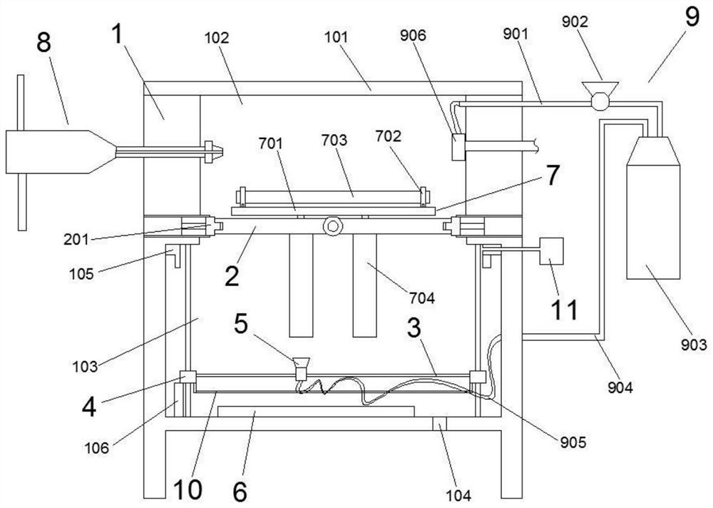
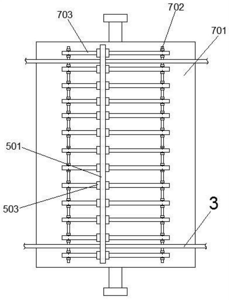
[0045] Such as Figure 1-4 As shown, a cleaner for ophthalmic vitrectomy tubes includes a cleaning box 1, the top of the cleaning box 1 is provided with an openable closed end cap 101, and a telescopic fixed platform 7 is arranged inside the cleaning box 1. The telescopic fixed platform 7 includes a telescopic mechanism 704 to drive it to stretch out or retract the fixed plate 701 of the cleaning box 1. On the fixed plate 701, several groups of clamps 702 for clamping and fixing the vitrified tube 703 to be cleaned are distributed;

[0046] A freezing device 8 is provided in the cleaning box 1, and the freezing device 8 reduces the temperature of the vitrified tube 703 to minus 10-20°C, so that the residual dirt on the vitrified tube 703 is frozen;

[0047] In the cleaning box 1, an ultrasonic vibrating assembly 5 for ultrasonic descaling of the vitrified tube 703 is provided, and the ultrasonic vibrating assembly 5 reciprocates on the horizontal reciprocating screw mechanism ...

Embodiment 2

[0056] This embodiment is an optimization scheme based on Embodiment 1, its main structure is the same as that of Embodiment 1, and the improvements are as follows: figure 1 As shown, the cleaning box 1 is provided with a reversible carrying platform 2, and the reversible carrying platform 2 cooperates with the retractable clamps 201 on both sides of the cleaning box 1 to divide the cleaning box 1 into an upper freezing chamber 102. and the lower heating chamber 103 , the telescopic mechanism 704 of the telescopic fixed platform 7 is fixed on the upper surface of the reversible carrier 2 , and makes it turn over with the reversible carrier 2 .

[0057] In this embodiment, the telescopic clamping plate 201 is actually two plates arranged on both axial sides of the turning axis of the reversible platform 2, and these two plates can be stretched out into the cleaning box respectively under the drive of the cylinder. In the cavity of the body 1 or retracted into the side wall of t...

Embodiment 3

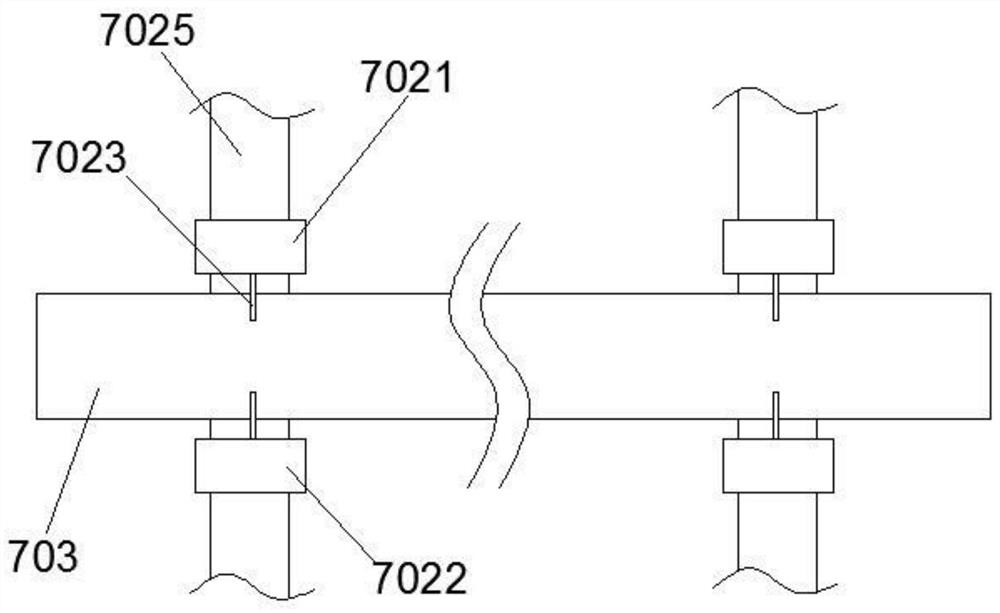
[0059] This embodiment is another optimization scheme made on the basis of embodiment 1, and its main structure is the same as that of embodiment 1, and the improvements are as follows: Figure 2-4 As shown, each set of clamps 702 includes two symmetrical clamping units, each clamping unit includes a symmetrically arranged fixed clamping plate 7022 and a movable clamping plate 7021, and the fixed clamping plate 7022 and the movable clamping plate The opposite side of 7021 has an arc-shaped clamping knife 7023, and the bottom of the movable clamping plate 7021 is slidably arranged on the slide rail 7025 on the surface of the fixed plate 701, and is arranged between the fixed clamping plate 7022 and the movable clamping plate 7021 There is a manual adjustment bolt 7024, by turning the manual adjustment bolt 7024 to adjust the distance between the fixed clamping plate 7022 and the movable clamping plate 7021, thereby completing the clamping of the vitrified tube 703.

[0060] In ...


PUM


Abstract

The invention porvides a cleaning device for an ophthalmology vitrectomy tube. The cleaning device comprises a cleaning box body internally provided with a telescopic fixing platform, wherein the telescopic fixing platform comprises a fixing plate which is driven by a telescopic mechanism to stretch out of or retract into the cleaning box body, and clamps used for clamping and fixing the vitrectomy tube are distributed on the fixing plate; a freezing device used for freezing the glass cutting tube, an ultrasonic vibration assembly used for carrying out ultrasonic descaling on the glass cutting tube, and a heating assembly is used for gasifying dirt after descaling. The method comprises the following steps: firstly, enabling the glass cutting tube to be in a low-temperature environment so as to freeze the residual dirt to form a solid, then enabling the glass cutting tube and the frozen dirt to resonate at different frequencies by utilizing an ultrasonic resonance principle so as to complete the separation, crushing and micronization of the dirt, and finally, gasifying the micronized dirt by utilizing rapid temperature rise, so that the integrated operation of cleaning, sterilizing and disinfecting is completed, and the advantages of high cleaning efficiency and good effect are achieved.

Description

technical field [0001] The invention relates to a vitrectomy tube used for vitreous humor removal in ophthalmic surgery, in particular to a cleaner for the ophthalmic vitrectomy tube. Background technique [0002] The vitreous is a semi-solid gel-like substance in the eye that fills the vitreous cavity. Under normal circumstances, the vitreous has good light transmission, so that the retina and choroid are attached. If the vitreous body has lesions, the mild ones will feel mosquitos flying in front of the eyes when looking at things, and the severe ones can completely block the light and become blind. It may also cause surrounding tissue lesions, such as retinal detachment, and damage the entire eyeball. The basic role of vitrectomy is to remove the opaque vitreous body or remove the vitreoretinal traction, restore the transparent refractive medium and promote retinal reattachment, treat vitreoretinal diseases, and restore the patient's visual function. [0003] The cuttin...

Claims


Application Information

Patent Timeline
Patent Type & Authority Applications(China)
IPC IPC(8): A61B90/70F26B23/06
CPCA61B90/70F26B23/06
Inventor 潘丽刘董王晓辉
Owner THE FIRST AFFILIATED HOSPITAL OF HENAN UNIV OF SCI & TECH
Why Eureka
Try Eureka