A carbon fiber recycling device and carbon fiber recycling method

A recycling device and recycling method technology, applied in the field of material processing, can solve the problems of less research on carbon fiber metal composite material recycling, large scope, and high manufacturing difficulty.

Active Publication Date: 2022-05-17
南京智海科技有限公司
View PDF9 Cites 0 Cited by
  • Summary
  • Abstract
  • Description
  • Claims
  • Application Information

AI Technical Summary

Problems solved by technology

Because the application of carbon fiber metal is not as extensive as that of resin-based carbon fiber polymer composite materials, and the production of carbon fiber metal composite materials is more difficult, so there are few researches on the recycling of carbon fiber metal composite materials.

Method used


Image

  • A carbon fiber recycling device and carbon fiber recycling method
  • A carbon fiber recycling device and carbon fiber recycling method
  • A carbon fiber recycling device and carbon fiber recycling method

Examples


Embodiment 1

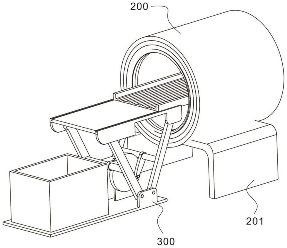
[0034] refer to Figure 1~4 , which is the first embodiment of the present invention, provides a carbon fiber recycling device and a carbon fiber recycling method, the device includes an induction heating assembly 100, a heating cavity 200 and a material dumping assembly 300, wherein the induction heating assembly 100 includes a rectifier 101, A filter 102 connected in series with the rectifier 101, an inverter 103 connected in series with the filter 102, a rectification control circuit 104 connected in parallel with the rectifier 101, and an inverter control circuit 105 connected in parallel with the inverter 103 and power supply 106;

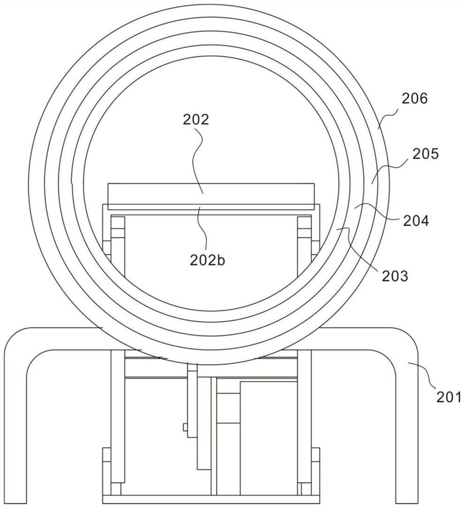
[0035] The heating cavity 200 includes a bracket 201, a processing table 202 fixedly connected to the bracket 201, an induction coil 203, a cylinder 204 sleeved outside the induction coil 203, and a partition sleeved outside the cylinder 204. The thermal cloth 205 and the casing 206 sleeved outside the thermal insulation cloth 205; and,

[0...

Embodiment 2

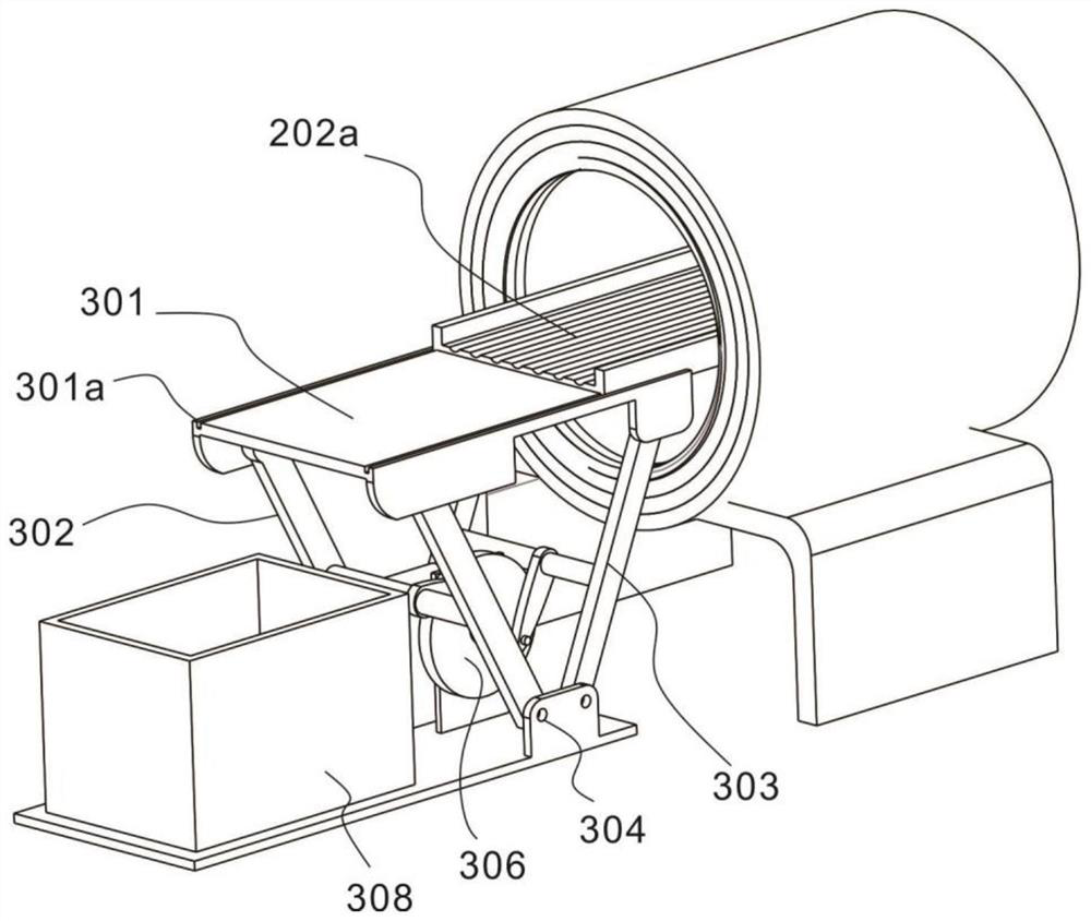
[0041] refer to Figure 1-8 , is the second embodiment of the present invention, which is different from the first embodiment in that: the processing table 202 is made of ceramics, and the surface is also provided with a groove 202a parallel to the longitudinal direction of the heating chamber 200, and A limiting plate 202b is provided at its end.

[0042] Compared with Embodiment 1, further, the outer surface of the entire heating chamber 200 is a layer of metal round wall shell 206, and the metal round wall shell 206 is welded on the bracket 201 by welding, and the function of the metal round wall is mainly The structure inside the heating chamber 200 is protected to prevent collisions during transportation, installation and use.

[0043] Inside the shell 206 is a layer of thermal insulation cloth 205 made of ceramic fiber cloth, which can play a role in heat preservation and heat insulation, and reduce the loss of energy. At the same time, the ceramic fiber cloth can bette...

Embodiment 3

[0050] refer to Figure 1-8 , is the third embodiment of the present invention, and this embodiment is different from the second embodiment in that: the surface of the mobile table 301 is provided with a sliding groove 301a cooperating with the processing table 202, the bottom is provided with a guide groove 301b, and the first One end of the connecting rod 302 connected to the guide groove 301b is provided with a guide wheel 302a, and the guide wheel 302a slides in cooperation with the guide groove 301b, and one end of the second connecting rod 303 connected to the mobile platform 301 is hinged.

[0051] A rotating shaft 303 a is connected between the first connecting rod 302 and the second connecting rod 303 , the rotating shaft 303 a is hinged to the connecting shaft 307 , and the other end of the connecting shaft 307 is hinged to the turntable 306 . The output shaft of the motor 305 is connected with the center of the turntable 306 .

[0052] Compared with Embodiment 2, f...


PUM


Abstract

The invention discloses a carbon fiber recycling device and a carbon fiber recycling method. The device includes an induction heating component, including a rectifier, a filter connected in series with the rectifier, an inverter connected in series with the filter, a rectification control circuit connected in parallel with the rectifier, and an inverter. The inverter control circuit and power supply connected in parallel with the inverter; the heating cavity, including the support, the processing table fixedly connected with the support, the induction coil, the cylinder sleeved outside the induction coil, the heat insulation cloth sleeved outside the cylinder and The shell is sleeved on the outside of the heat-insulating cloth; and, the unloading assembly includes a mobile platform that is slidably connected to the processing platform, a first connecting rod and a second connecting rod that are symmetrically arranged on both sides of the mobile platform, and the first connecting rod The base hinged with the second connecting rod, the motor set on the base, the turntable, the connecting shaft hinged with the turntable, and the dump bin set under the moving table; the invention can quickly and efficiently melt the metal base material on the carbon fiber surface, And the waste material is cleaned through the dumping component, so as to achieve the purpose of recycling carbon fiber.

Description

technical field [0001] The invention relates to the technical field of material processing, in particular to a carbon fiber recovery device and a carbon fiber recovery method. Background technique [0002] Carbon fiber metal composite material is a composite material formed by using carbon fiber or carbon fiber fabric as reinforcement and different metals as matrix. Carbon fiber metal composite materials have excellent properties such as high specific strength and specific modulus, good anti-friction and electrical conductivity, and good corrosion resistance. and sliders are widely used. With the widespread use of carbon fiber metal composite reinforced materials, the waste metal composite materials generated are increasing rapidly, including scraps generated in the manufacturing stage and scrap products at the end of their service life. On the one hand, the generated waste occupies industrial land and pollutes the environment. On the other hand, the carbon fiber in the ca...

Claims


Application Information

Patent Timeline
Patent Type & Authority Patents(China)
IPC IPC(8): B09B3/00B09B3/35B09B3/40B09B5/00B09B101/85
CPCB09B3/00B09B5/00Y02W30/62
Inventor 刘志强张家俊
Owner 南京智海科技有限公司
Why Eureka
Try Eureka