Grinding device for mechanical parts

A technology for mechanical parts and machinery, applied in the field of grinding devices for mechanical parts, can solve the problems of cumbersome grinding operations for mechanical parts, low grinding efficiency of mechanical parts, and difficulty in guaranteeing quality, etc. Easy-to-use sanding effect

Inactive Publication Date: 2021-05-28
广州市魅雅特贸易有限公司
View PDF4 Cites 7 Cited by
  • Summary
  • Abstract
  • Description
  • Claims
  • Application Information

AI Technical Summary

Problems solved by technology

The traditional way of grinding mechanical parts is to grind the surface of mechanical parts with a hand-held grinder. This method is not only inefficient, but also consumes a lot of manpower during the grinding process. It is more affected by human factors, resulting in the production of mechanical parts. The error is relatively large, and the quality is difficult to guarantee, so it cannot meet the actual needs of large-scale mechanical parts production; at the same time, the existing grinding device for mechanical parts only drives the mechanical parts or the grinding block to rotate for the grinding of mechanical parts. During the grinding process of mechanical parts, the position of mechanical parts needs to be moved artificially, which not only leads to low efficiency of mechanical parts grinding, but also makes the grinding operation of mechanical parts more cumbersome, which is not conducive to the actual production of mechanical parts; finally, existing machinery The grinding device for parts can only grind a single type of mechanical parts, resulting in a small range of application and poor practicability of the equipment, which cannot meet the actual needs of mechanical parts production

Method used


Image

  • Grinding device for mechanical parts
  • Grinding device for mechanical parts
  • Grinding device for mechanical parts

Examples


Embodiment Construction

[0031] The following will clearly and completely describe the technical solutions in the embodiments of the present invention with reference to the accompanying drawings in the embodiments of the present invention. Obviously, the described embodiments are only some, not all, embodiments of the present invention. Based on the embodiments of the present invention, all other embodiments obtained by persons of ordinary skill in the art without creative efforts fall within the protection scope of the present invention.

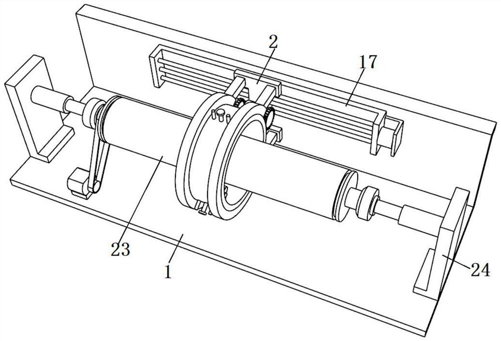
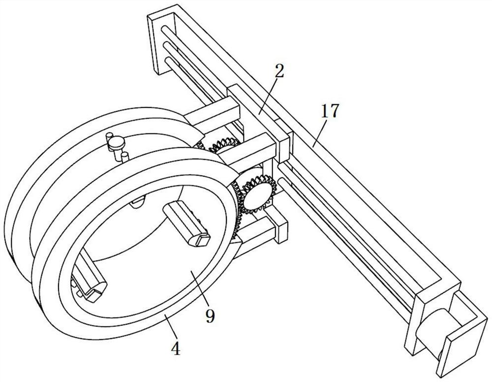
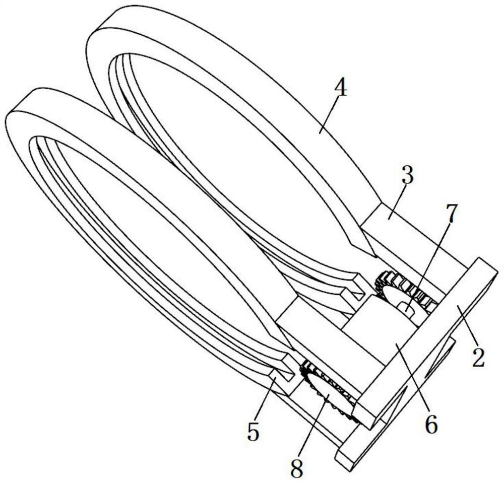
[0032] see Figure 1-8, the present invention is a grinding device for mechanical parts, comprising a support base 1, a group of clamping mechanisms are fixed on the support base 1, a mechanical pipe 23 is fixed between the two clamping mechanisms, and the two clamping mechanisms are symmetrically distributed with respect to the mechanical pipe 23 Such setting can ensure that the two clamping mechanisms can effectively and stably clamp the mechanical pipe fitting 2...


PUM


Abstract

The invention discloses a grinding device for mechanical parts, and relates to the technical field of mechanical part machining. The grinding device for the mechanical parts comprises a supporting seat, wherein a group of clamping mechanisms is fixed on the supporting seat, a mechanical pipe fitting is fixed between the two clamping mechanisms, the two clamping mechanisms are symmetrically distributed about the mechanical pipe fitting, a grinding mechanism is fixed to one surface of the supporting seat, and connected outside the mechanical pipe fitting in a sleeved mode, and the grinding mechanism comprises a transmission assembly and a sleeve. According to the invention, a first single-shaft motor in the transmission assembly is controlled to run, so that the first single-shaft motor drives a threaded lead screw to rotate, a plurality of grinding blocks are driven to move along the mechanical pipe fitting to be ground in the mode of lead screw transmission, the plurality of grinding blocks can be driven by a double-shaft motor to rotate in the mode of gear transmission, then effective grinding treatment is carried out on the mechanical pipe fitting, and the grinding operation for the mechanical pipe fitting is simpler and more convenient, so that the grinding efficiency for the mechanical pipe fitting is increased, and manpower consumption in the grinding process for the mechanical pipe fitting is reduced.

Description

technical field [0001] The invention belongs to the technical field of mechanical parts processing, in particular to a grinding device for mechanical parts. Background technique [0002] Mechanical parts, also known as mechanical components, are the basic components of machinery. They are inseparable individual parts that make up machinery and machines. General term. Since the emergence of machinery, there have been corresponding mechanical parts. But as a discipline, mechanical parts are separated from mechanical construction and mechanics. With the development of the machinery industry, the emergence of new design theories and methods, new materials, and new processes, mechanical parts have entered a new stage of development. [0003] Mechanical parts are widely used in various fields. They play a vital role in modern production and life. The combination of mechanical parts constitutes a complex machine. The use of machines can not only significantly improve production ...

Claims


Application Information

Patent Timeline
Patent Type & Authority Applications(China)
IPC IPC(8): B24B5/04B24B41/06B24B47/12B24B47/04
CPCB24B5/04B24B41/062B24B47/12B24B47/04
Inventor 朱烁航朱晓明
Owner 广州市魅雅特贸易有限公司
Why Eureka
Try Eureka