
L-shaped shallow sea pipeline laying process

A pipeline laying and pipeline technology, which is applied in the field of L-shaped shallow sea pipeline laying technology, can solve the problems of low construction efficiency of towed pipeline laying construction technology, complex and changeable construction operation environment, large influence of wind and wave conditions, etc., and achieves construction operation conditions. Stable and reliable, improving the efficiency of pipeline laying, the effect of long construction window period

Pending Publication Date: 2021-05-28
CCCC THIRD HARBOR ENG
View PDF6 Cites 2 Cited by
  • Summary
  • Abstract
  • Description
  • Claims
  • Application Information

AI Technical Summary

Problems solved by technology

[0004] Due to the large dead weight and large diameter of large-diameter pipelines in the sea, and the complex and changeable offshore construction environment, it is difficult to carry out construction operations in shallow sea areas. Existing dedicated pipeline laying ships cannot carry out construction operations in shallow sea areas. However, the towed pipeline laying method commonly used in shallow sea area pipeline laying construction has the problems of low construction efficiency and great influence of sea wind and waves.
[0005] In view of the fact that the existing towed pipeline laying construction technology has low construction efficiency and is greatly affected by wind and wave conditions during construction operations, a pipeline laying construction technology that can improve the construction efficiency of pipeline laying in shallow sea areas and reduce the impact of wind and waves is needed

Method used


Image

  • L-shaped shallow sea pipeline laying process
  • L-shaped shallow sea pipeline laying process
  • L-shaped shallow sea pipeline laying process

Examples


Embodiment 1

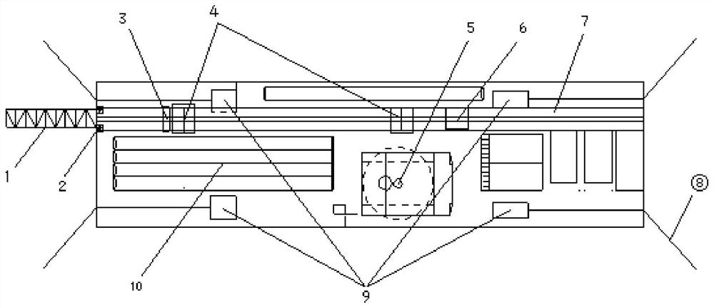
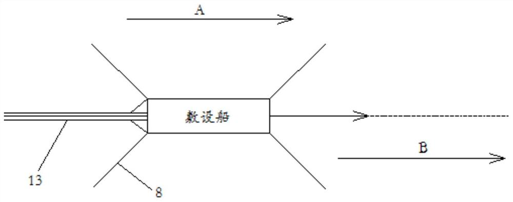
[0036] Embodiment 1, with reference to figure 1 , a kind of " L " type shallow sea pipeline laying technology provided by the present invention, by adopting the shallow sea area pipeline laying special vessel to carry out pipeline laying installation work, use windlass 9 installed on the barge to control the construction route of pipeline laying.

[0037] The special ship for pipeline laying in shallow sea area includes a hull, on which a guide frame 7 is fixed, on which a track is arranged along the direction of the hull keel, and in front of the guide frame 7 is provided with a stinger 1 protruding from the hull. The rear end of the frame 1 is hinged with the front end of the hull; a clamper 3 is fixedly installed between the guide frame 7 and the stinger frame 1, and the clamper 3 can realize the clamping and release of the pipeline 11, thereby controlling the flow of the pipeline 11. speed. A welding platform 4 for butt jointing of pipelines 11 is provided on the guide fr...


PUM

PropertyMeasurementUnit
Lengthaaaaaaaaaa

Abstract

The invention discloses an L-shaped shallow sea pipeline laying process, and relates to the technical field of pipeline laying engineering. The L-shaped shallow sea pipeline laying process comprises the following steps of towing a pipeline laying ship to a pipeline laying axis position, carrying out anchoring by an anchoring ship, and adjusting the pipeline laying ship to the designed pipeline laying axis center position; hoisting two sections of steel pipes to a guide frame for pipeline laying, enabling the pipe sections to slide downwards to a pipeline welding platform along a track of the guide frame, and welding the two sections of steel pipes into a pipeline; enabling the pipeline to slide downwards to a stinger, and fixing the pipeline through a clamping device; hoisting a next pipe section to the guide frame, and completing welding of the pipe section and the pipeline on the welding platform; loosening the pipe clamping device, and enabling the first two sections of pipelines to enter water by adopting a water injection method; enabling the pipeline laying ship to move backwards and retreat, and enabling the pipeline to slide down to the seabed along the stinger; and repeating the procedures of fixing, hoisting, welding and lowering until all pipelines are laid. According to the L-shaped shallow sea pipeline laying process, the construction efficiency of offshore pipeline laying can be improved, the influence of environmental factors on pipeline laying construction operation is reduced, the effect is good, and the positioning precision is higher.

Description

technical field [0001] The invention relates to the technical field of pipeline laying engineering, in particular to an L-shaped shallow sea pipeline laying process. Background technique [0002] At present, the construction ships and machinery equipment used in offshore pipeline laying are mainly dedicated pipeline laying vessels, and the formulation of construction plans is mainly carried out around the pipeline laying vessels. As the offshore water supply and drainage pipeline laying project gradually moves from the nearshore area to the shallow sea area, it is inevitable to lay municipal water supply and drainage pipelines in the shallow sea area. Most of the currently available dedicated pipeline laying ships are manufactured for offshore oil pipeline laying in deep sea areas, and there are no special construction ships that can be used for pipeline laying in shallow sea areas. Therefore, for pipeline laying projects in shallow sea areas, it is necessary to formulate a...

Claims


Application Information

Patent Timeline
IPC IPC(8): F16L1/16F16L1/20F16L1/235B63B35/03
CPCF16L1/16F16L1/235F16L1/202B63B35/03
Inventor 皋黎明程加军范旭征博董志芳裴延庚赵刚李宁
Owner CCCC THIRD HARBOR ENG
Learn More