Eureka AIR delivers breakthrough ideas for toughest innovation challenges, trusted by R&D personnel around the world.

Rotor punching sheet structure

A rotor punching and punching technology, applied in the field of new energy vehicle motors, can solve the problems of high risk, weak strength, inability to take into account high efficiency, low noise, high speed and cost reduction, and achieves low cost, reduced stress, and improved The effect of utilization

Pending Publication Date: 2021-05-28
HEFEI JUYI POWER SYST CO LTD
View PDF1 Cites 0 Cited by
  • Summary
  • Abstract
  • Description
  • Claims
  • Application Information

AI Technical Summary

Problems solved by technology

[0005] In the motor rotor punching solution of Patent Document 1, a magnetic steel groove, an auxiliary groove, a magnetic bridge, and a harmonic-removing hole are arranged on the rotor punching body, and through the magnetic steel groove, auxiliary groove, magnetic bridge, and harmonic-removing hole, The design of the distribution method improves the strength of the motor rotor punching. On the basis of satisfying the motor power and torque performance, it solves the problem caused by the decrease of the yield strength of the rotor punching due to the increase of the temperature of the motor rotor during the continuous high-speed rotation of the motor. The problem of weak strength and high risk, but it cannot take into account the problems of high efficiency, low noise, high speed and cost reduction

Method used


Image

  • Rotor punching sheet structure
  • Rotor punching sheet structure
  • Rotor punching sheet structure

Examples


Embodiment Construction

[0042] In order to make the technical solutions and advantages of the present invention clearer, the present invention will be further described below in conjunction with the accompanying drawings and embodiments.

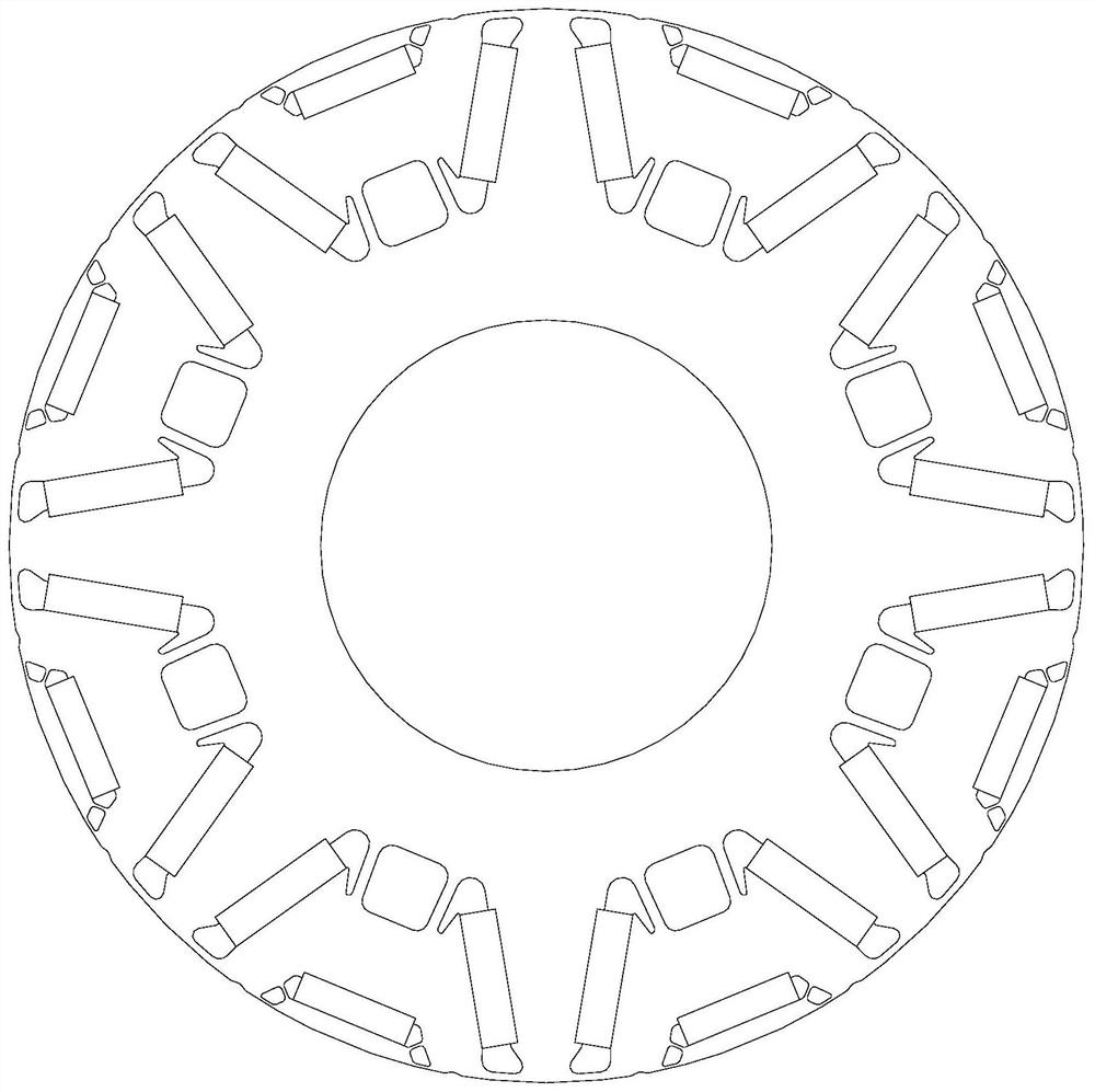
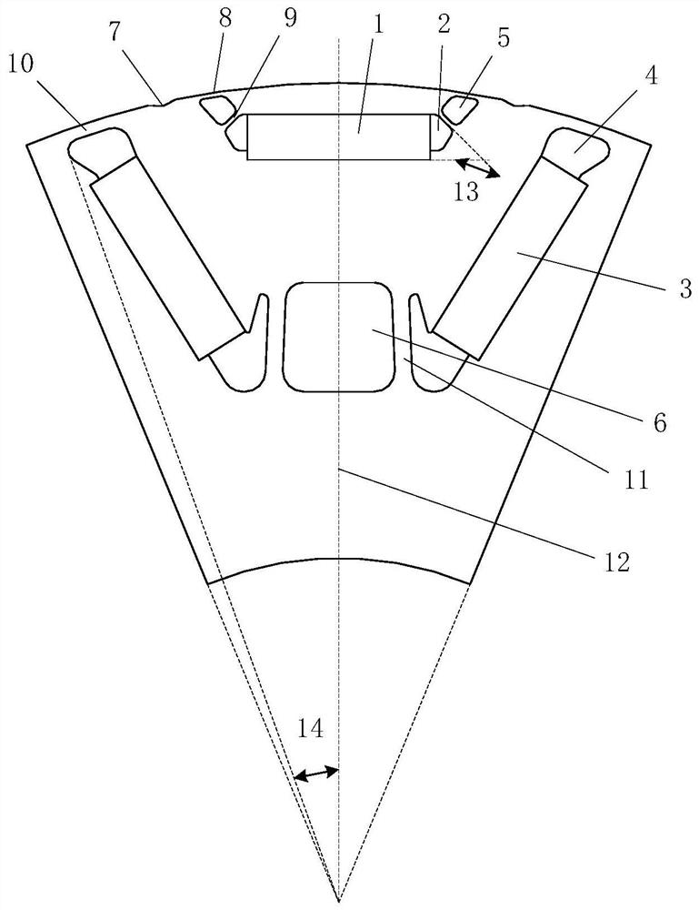
[0043] Such as figure 1 and figure 2 As shown, the present invention provides a rotor punching structure, including a punching body, on which a plurality of magnetic poles distributed symmetrically along the circumferential direction are arranged, and each magnetic pole includes a first magnetic steel groove 2, two The second magnetic steel slot 4 , two first air slots 5 and one second air slot 6 .

[0044] The first magnetic steel groove 2 is symmetrical about the D-axis center line 12, and the first magnetic steel groove 2 is installed with the first magnetic steel 1; two first air grooves 5 are symmetrically distributed on the outer sides of the two ends of the first magnetic steel groove 2 ; The first air groove 5 and the outer circle of the stamping body fo...


PUM


Abstract

The invention discloses a rotor punching sheet structure comprising a punching sheet body which is provided with a plurality of magnetic poles symmetrically distributed along the circumferential direction. Each magnetic pole comprises a first magnetic steel groove which is symmetrical by taking the center line of the D axis as the center, two second magnetic steel grooves which are symmetrically distributed in a V shape by taking the center line of the D axis as the center, two first air grooves which are symmetrically distributed in the outer sides of the two ends of the first magnetic steel groove, and a second air groove which is located in the middle of the proximal ends of the two second magnetic steel grooves; the first air grooves and the outer circle of the punching sheet body form a first magnetic bridge, and a second magnetic bridge is formed between the first magnetic steel grooves and the first air grooves. The telecentric ends of the second magnetic steel grooves and the outer circle of the punching sheet body form a third magnetic bridge, and the proximal end of the second magnetic steel groove and the second air groove form a fourth magnetic bridge. Through the innovative design, the rotor punching sheet structure has the remarkable advantages of high efficiency, high performance, low noise, high rotating speed and low cost.

Description

technical field [0001] The invention relates to the field of new energy vehicle motors, in particular to a rotor punching structure. Background technique [0002] Permanent magnet synchronous motor, as the most important motor type of new energy vehicle drive motor, has the outstanding advantages of high efficiency and high performance. Low-noise, high-speed, and low-cost electromagnetic solutions are the difficulties in the design of electromagnetic solutions in the future. [0003] As the core component of the permanent magnet synchronous motor, the rotor punching directly determines the performance, cost, noise and other key indicators of the motor solution. Traditional permanent magnet motor rotor punching often cannot take care of all the above key indicators. [0004] Published patent document 1 (publication number CN 111654133 A) discloses a motor rotor punching and motor rotor assembly system, the motor rotor punching includes the rotor punching body, with multiple...

Claims


Application Information

Patent Timeline
Patent Type & Authority Applications(China)
IPC IPC(8): H02K1/27H02K1/28H02K21/02
CPCH02K1/27H02K1/28H02K21/028H02K2213/03H02K1/2766H02K1/276H02K2201/03Y02T10/64
Inventor 刘蕾张仁忠范坤
Owner HEFEI JUYI POWER SYST CO LTD
Why Eureka
Eureka Blog
Learn More