Eureka AIR delivers breakthrough ideas for toughest innovation challenges, trusted by R&D personnel around the world.

System and method for treating waste water containing volatile substances

A technology for volatile substances and treatment systems, applied in the field of treatment systems for wastewater containing volatile substances, can solve problems such as difficult operation, excessive expansion of wastewater water volume, and large consumption of circulating water, so as to save steam consumption and energy consumption , the effect of saving consumption

Pending Publication Date: 2021-06-01
BEIJING CYCLE COLUMBUS ENVIRONMENTAL TECH RES INST CO LTD
View PDF8 Cites 2 Cited by
  • Summary
  • Abstract
  • Description
  • Claims
  • Application Information

AI Technical Summary

Problems solved by technology

If steam is directly used as a heat source, it will cause the waste water to expand too much, which will increase the subsequent treatment cost of waste water
These two methods have problems such as large steam consumption, difficult reuse of condensed water, and large amount of circulating water.
[0003] Patent CN207046874 U proposes a recycling treatment system for recovering ammonia from ammonia-nitrogen waste water, which mainly uses ammonia gas at the top of the tower as a heat source to heat the tower kettle to save steam consumption. The disadvantages are: 1) Ammonia is alkaline, which requires high anti-corrosion requirements for compressors and reboilers, resulting in high investment in equipment
2) If the heat exchange equipment is corroded, it will affect the quality of recovered ammonia water
3) It is necessary to strictly control the gas volume and temperature of the ammonia gas to ensure the stability of the heat source of the reboiler, which makes the operation difficult and the conditions are harsh

Method used


Image

  • System and method for treating waste water containing volatile substances

Examples


Embodiment 1

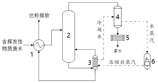
[0042] Ammonia nitrogen wastewater treatment system, such as figure 1 As shown, it includes: preheater 1, stripping rectification tower 2, reboiler 3, primary condenser 4, secondary condenser 5 and compressor 6, preheater 1 is provided with untreated waste water inlet, untreated Treated waste water outlet, treated waste water inlet and treated waste water outlet, stripping rectification tower 2 is provided with waste water inlet, tower kettle waste water outlet, waste water vaporized steam inlet and tower top ammonia-containing steam outlet, reboiler 3 is provided with waste water inlet , compressed water vapor inlet, treated waste water outlet, waste water vaporization steam outlet and condensed water outlet, the primary condenser 4 is provided with ammonia-containing steam inlet, condensed water inlet, ammonia water outlet and steam outlet, and the secondary condenser 5 is provided with Ammonia water inlet and ammonia water product outlet, compressor 6 is provided with water...

Embodiment 2

[0064] The treatment system and treatment method of ammonia nitrogen wastewater are the same as in Example 1, and the operating parameters of the stripping and rectifying tower are shown in Table 2.

[0065] Table 2 Operating parameters of the stripping distillation column

[0066] Ammonia-containing wastewater inlet flow rate of deammonization tower 125m 3 / h

Ammonia-containing wastewater inlet temperature of deamination tower 90-95℃ Ammonia-containing vapor at the top of the deamination tower 11.1t / h [range 8.3~28.5t / h] Ammonia-containing vapor temperature at the top of the deamination tower 95~100℃ Composition of ammonia-containing vapor at the top of the deammonization tower Ammonia 20%, water vapor 80% The temperature of ammonia water recovered from the top of the tower after being condensed by the top condenser 35℃ Amount of steam consumed by deamination tower (direct heating) About 13t / h, subject to 0.4MPa saturated s...

Embodiment 3

[0073] Treatment systems for ethanol-containing wastewater, such as figure 1 As shown, it includes: preheater 1, stripping rectification tower 2, reboiler 3, primary condenser 4, secondary condenser 5 and compressor 6, preheater 1 is provided with untreated waste water inlet, untreated Treated waste water outlet, treated waste water inlet and treated waste water outlet, stripping rectification tower 2 is provided with waste water inlet, tower kettle waste water outlet, waste water vaporization steam inlet and tower top ethanol-containing steam outlet, reboiler 3 is provided with waste water inlet , compressed water vapor inlet, treated waste water outlet, waste water vaporization steam outlet and condensed water outlet, the primary condenser 4 is provided with ethanol-containing steam inlet, condensed water inlet, ethanol outlet and water vapor outlet, and the secondary condenser 5 is provided with Ethanol inlet and ethanol product outlet, compressor 6 is provided with water v...


PUM


Abstract

The invention discloses a system and method for treating waste water containing volatile substances and belongs to the technical field of waste water treatment. The treatment system comprises a preheater, a steam stripping rectifying tower, a reboiler, a primary condenser, a secondary condenser and a compressor. The treatment method comprises the following steps: (1) preheating the wastewater in the preheater; (2) feeding the preheated wastewater into a steam stripping rectifying tower, and indirectly heating the tower kettle wastewater into a reboiler by compressed water vapor to obtain wastewater vaporized steam and treated wastewater; (3) feeding waste water vaporized steam into the steam stripping rectifying tower to serve as a tower kettle heat source, and enabling volatile substance-containing steam to escape from the tower top and to enter the primary condenser to be condensed; (4) further performing condensing in the secondary condenser to obtain a condensed volatile product; (5) feeding the treated wastewater into the preheater for heat exchange, and then discharging the wastewater after the wastewater reaches the standard; and (6) after the wastewater is heated by the compressed water vapor in the step (2) to form condensed water, feeding the condensed water into the primary condenser to be heated and gasified to generate water vapor, enabling the vapor to enter the compressor, performing pressurizing and heating to form compressed water vapor, and feeding the vapor into the reboiler for circulation.

Description

technical field [0001] The invention belongs to the technical field of wastewater treatment, and relates to a treatment system and method for wastewater containing volatile substances. Background technique [0002] Wastewater containing volatile substances (such as ammonia nitrogen wastewater, ethanol-containing wastewater, methanol-containing wastewater, and other wastewater containing organic volatile substances) widely adopts stripping and rectification technology to remove volatile substances in wastewater. Taking ammonia nitrogen wastewater as an example, the current stripping and rectifying ammonia removal technology is a mature and widely used technology. The traditional process usually uses a reboiler as a heat source or directly injects saturated steam as a heat source. When a reboiler is used as a heat source, the steam directly turns into condensed water after passing through the reboiler. If steam is directly used as a heat source, it will cause excessive expans...

Claims


Application Information

Patent Timeline
Patent Type & Authority Applications(China)
IPC IPC(8): C02F1/04C02F1/20C02F1/58C02F101/30
CPCC02F1/04C02F1/20C02F1/586C02F1/58C02F2101/30
Inventor 李雅赵宇婧王启伟李金涛李志强
Owner BEIJING CYCLE COLUMBUS ENVIRONMENTAL TECH RES INST CO LTD
Why Eureka
Eureka Blog
Learn More