
A prechamber ignition internal combustion engine controlled by jet valve

A pre-combustion chamber and jet valve technology, applied to internal combustion piston engines, combustion engines, mechanical equipment, etc., can solve the problems of increasing jet ignition energy, throttling loss and heat loss, early combustion of internal combustion engines, etc., to reduce combustion Effects of cycle fluctuation, volume reduction, and life extension

Active Publication Date: 2022-04-29
烟台安信精冲技术有限公司
View PDF14 Cites 1 Cited by
  • Summary
  • Abstract
  • Description
  • Claims
  • Application Information

AI Technical Summary

Problems solved by technology

[0005] First, whether it is an active pre-chamber or a passive pre-chamber, the communication channel between the pre-chamber and the main combustion chamber allows the jet gas to pass through. When the pilot mixture is ignited, the high-temperature and high-pressure jet gas generated by it passes through all The channel is used to heat the channel, especially the nozzle hole facing the main combustion chamber; when the main mixed gas is ignited by the jet gas, high temperature and high pressure gas is generated in the main combustion chamber, and the gas pressure is higher than that of the pre-combustion chamber pressure, the high temperature and high pressure gas flows from the main combustion chamber into the pre-combustion chamber reversely, and heats it for the second time through the passage and nozzle hole; when the piston expands and descends, the pressure of the main combustion chamber drops, and the high-temperature gas in the pre-combustion chamber is reheated. Pass through the channel and injection hole once to reach the main combustion chamber, and heat it for the third time, so that the channel and injection hole are in a high-heat state, and the channel and injection hole in a high-heat state will cause early combustion of the internal combustion engine, resulting in pre-combustion chamber ignition failure
At the same time, the jet gas will also produce throttling loss when it passes through the nozzle hole many times.
[0006] Second, because there is no valve isolation between the pre-chamber and the main combustion chamber, after the pre-chamber is ignited, its pilot mixture is injected into the main combustion chamber immediately, and the jet gas temperature of the initial injection is not high, and due to the pilot mixture If the gas is lost, the final combustion pressure cannot reach a high enough level, so more mass of the pilot mixture is required, resulting in increased throttling loss and heat loss, and it will also cause fluctuations in the combustion timing of the main mixture, which may be advanced or delayed, resulting in cycle Increased Volatility, Decreased Efficiency
[0007] Third, some previous patents set cooling devices on the pre-combustion chamber, but all cooling devices are difficult to effectively cool the injection holes
[0009] Fifth, it is difficult to operate under low temperature cold start conditions
[0012] Second, the design and installation of the conduit are unfavorable for heat dissipation;
[0013] Third, the sealing surface on the conduit is prone to processing and assembly deformation and thermal deformation under installation and high temperature conditions, which seriously affects the sealing effect of the sealing surface;
[0014] Fourth, simply relying on one mode of ignition cannot satisfy various operating states of the internal combustion engine
The ignition of the pre-chamber can obviously delay the combustion center of gravity, which also brings the ability to resist knocking, but if it is delayed more, the ignition energy of the jet needs to be increased, which requires an increase in the volume of the pre-chamber

Method used


Image

  • A prechamber ignition internal combustion engine controlled by jet valve
  • A prechamber ignition internal combustion engine controlled by jet valve
  • A prechamber ignition internal combustion engine controlled by jet valve

Examples


Embodiment 1

[0141] A pre-combustion chamber ignition internal combustion engine controlled by a jet valve has a cylinder body, a cylinder head, a cylinder, a piston, a connecting rod, a crankshaft, intake and exhaust valves, an intake system, an exhaust system and an EGR system. The piston reciprocates in the cylinder, the piston pin hole on it is connected to one end of the connecting rod, and the other end of the connecting rod is connected to the crankpin of the crankshaft. The reciprocating motion of the piston pushes the crankpin to rotate around the center of the crankshaft and output power to the outside.

[0142] figure 1 As shown, the cavity between the inner peripheral wall of the cylinder 1, the top surface of the piston 2 and the lower end surface of the cylinder head 5 forms a main combustion chamber 4, and at least one intake valve is arranged on the top surface 3 of the main combustion chamber near the intake side, It is used for the intake air of the cylinder 1, and at lea...

Embodiment 2

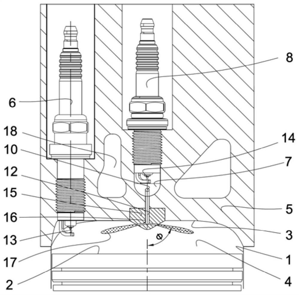
[0180] Figure 5 As shown, a jet valve-controlled pre-combustion chamber ignition internal combustion engine and its operating mode, for each cylinder of the internal combustion engine, a main spark plug 6 is respectively arranged on the side of the cylinder head 5 on the top surface 3 of the main combustion chamber , a pre-chamber 7, a pre-chamber spark plug 8, a jet valve 20, a one-way intake valve 90, a jet channel 12 leading from the pre-chamber 7 to the main combustion chamber 4, a jet passage 12 from the main combustion chamber 4 A passive intake channel 91 leading to the pre-chamber 7 , a valve nozzle 25 and at least one injection hole 16 . in:

[0181] The main spark plug 6 is arranged near the center of the cylinder 1 in the cylinder head 5 or on one side of the outer circumference of the cylinder 1, preferably on the outer circumference side of the cylinder 1, and the main spark plug electrode 13 faces the main combustion chamber 4, which can be used for Ignite the...

Embodiment 3

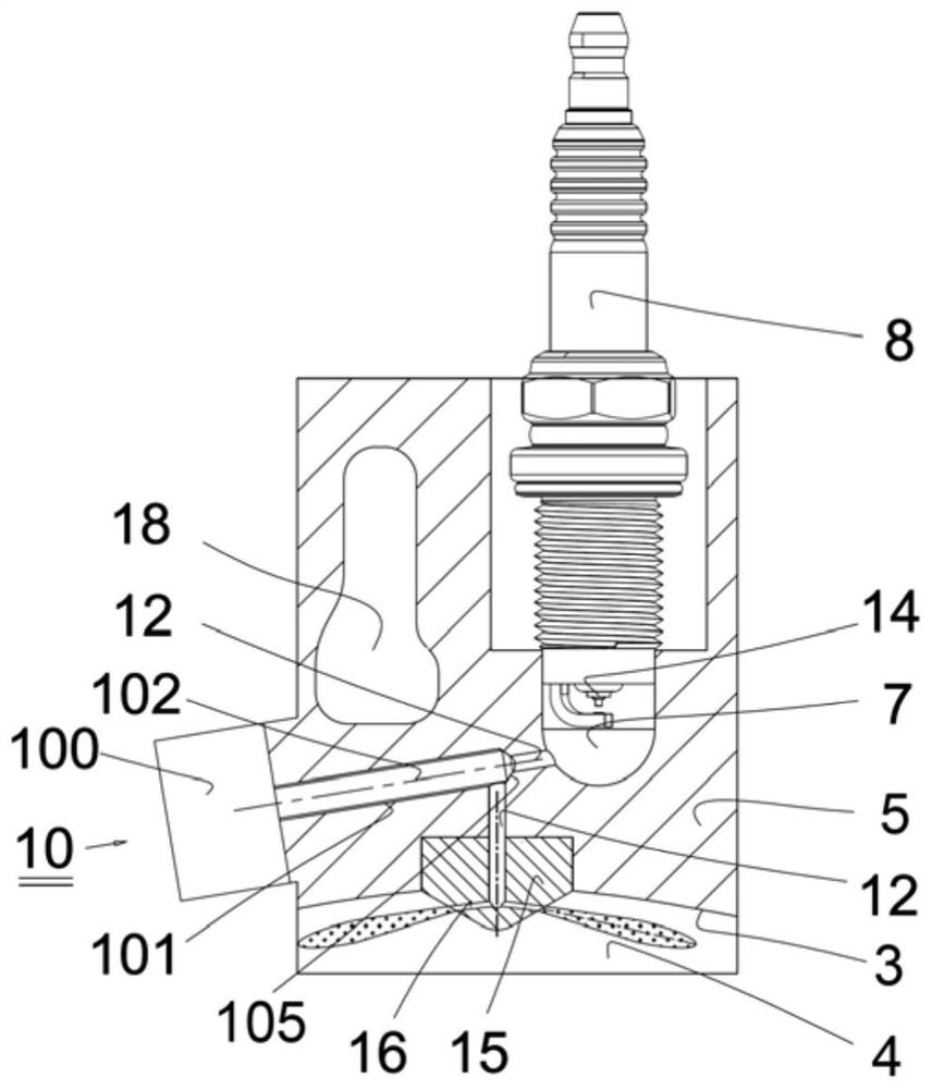
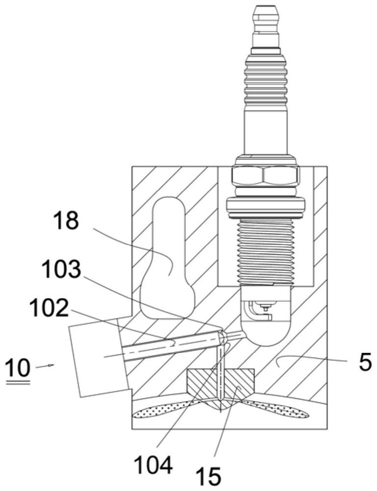
[0227] Figure 13 As shown, a jet valve-controlled pre-combustion chamber ignition internal combustion engine and its operating mode, for each cylinder of the internal combustion engine, a main spark plug 6 is respectively arranged on the side of the cylinder head 5 on the top surface 3 of the main combustion chamber , a pre-chamber 7, a pre-chamber spark plug 8, a jet valve 10, an intake valve 9, a jet channel 12 leading from the pre-chamber 7 to the main combustion chamber 4, a jet channel 12 leading from the intake valve 9 to the The active intake channel 11 of the prechamber 7 , a nozzle 15 and at least one injection hole 16 .

[0228] in:

[0229] The main spark plug 6 is arranged near the center of the cylinder 1 in the cylinder head 5 or on one side of the outer circumference of the cylinder 1, preferably on the outer circumference side of the cylinder 1, and the main spark plug electrode 13 faces the main combustion chamber 4, which can be used for Ignite the main mi...


PUM


Abstract

The invention provides a pre-chamber ignition internal combustion engine controlled by a jet valve, which is provided with a jet valve in the air flow passage between the pre-chamber and the main combustion chamber, and before the spark plug of the pre-chamber ignites the pilot mixture, the jet The valve is closed to cut off the gas channel from the pre-combustion chamber to the main combustion chamber. After the spark plug of the pre-combustion chamber ignites the pilot mixture and burns it for a period of time, the pilot mixture reaches the required high temperature and high pressure state. The best timing is always on, so that the high-temperature and high-pressure gas in the pre-combustion chamber is injected into the main combustion chamber and ignites the mixed gas in the main combustion chamber. Because the present invention adopts the jet valve, when the jet valve is closed, the ignition and combustion of the mixed gas in the pre-combustion chamber are not affected by the pressure, temperature, concentration and airflow movement of the mixed gas in the main combustion chamber, so that the ignition and combustion of the mixed gas in the pre-combustion chamber The combustion is carried out stably and the fluctuation of the combustion cycle is reduced.

Description

technical field [0001] The invention relates to an internal combustion engine technology, in particular to a pre-combustion chamber ignition internal combustion engine controlled by a jet valve. Background technique [0002] Ignition of the pre-chamber can significantly shorten the combustion duration of the mixture in the main combustion chamber, and can ignite the ultra-lean mixture, reduce the combustion temperature, reduce the emission of NOx, improve the combustion efficiency, and reduce the fuel consumption of the internal combustion engine. This is the main research on it in the world. reason. [0003] Pre-chamber ignition includes active pre-chamber and passive pre-chamber ignition, which means first igniting the mixed gas in the pre-chamber of the internal combustion engine, also known as pilot mixed gas, and passing the high-temperature and high-pressure gas generated by burning the pilot mixed gas through the pre-chamber The channel with the main combustion chamb...

Claims


Application Information

Patent Timeline
Patent Type & Authority Patents(China)
IPC IPC(8): F02B19/10F02B19/12
CPCF02B19/1033F02B19/1009F02B19/12Y02T10/12
Inventor 沈大兹刘琦关尽欢
Owner 烟台安信精冲技术有限公司
Learn More