Sheet-mounted tower, manufacturing and mounting method and wind turbine generator

A piece-mounted and tower-mounted technology, applied in the fields of manufacturing and installation methods and wind turbines, piece-mounted towers, and accessory modules, can solve electrical equipment damage, uneven force, and affect the load-bearing capacity of the tower and other problems, to achieve good fatigue resistance, eliminate micro-cracks, and improve the effect of geometric shape

Pending Publication Date: 2021-06-01
CRRC WIND POWER(SHANDONG) CO LTD
View PDF7 Cites 0 Cited by
  • Summary
  • Abstract
  • Description
  • Claims
  • Application Information

AI Technical Summary

Problems solved by technology

However, the height limit conditions of infrastructure such as roads and bridges (the standard height limit for primary and secondary roads is 5m), the relative concentration of infrastructure in geographical locations where decentralized projects are located, and the restrictions on transportation conditions in mountainous and hilly areas have led to large-diameter towers. The transportation conditions have become extremely harsh and even cannot be transported to the project site. Measures such as bridge demolition and road repair have caused huge costs and affected the project schedule requirements, and the bulky feature of the integral ring forged flange has limited the development of steel tubular towers , is also an important factor hindering the development of large-scale wind turbines
[0005] However, in the prior art, the structural setting for the connection of the tower pieces is unreasonable, resulting in inaccurate positioning during the assembly of the pieces, difficulty in connection, dislocation of the pieces, resulting in tilting of the tower, uneven force, and water leakage in the gaps. Damage to electrical equipment and cumbersome installation due to the diversity of accessories will affect the ability of the tower to bear loads and further affect the safety of wind turbines

Method used


Image

  • Sheet-mounted tower, manufacturing and mounting method and wind turbine generator
  • Sheet-mounted tower, manufacturing and mounting method and wind turbine generator
  • Sheet-mounted tower, manufacturing and mounting method and wind turbine generator

Examples


Embodiment 1

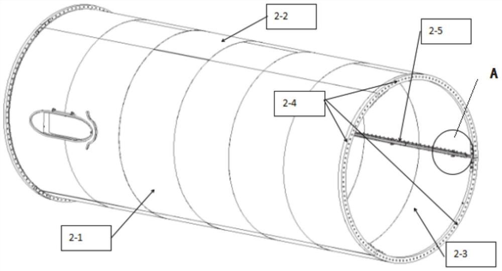
[0043] Such as figure 2 As shown, a sheet-mounted tower includes at least one sheet-mounted barrel section, the sheet-mounted barrel section includes a plurality of sheet bodies and a positioning connection structure, and the plurality of sheet bodies are connected through a positioning connection structure; if There are multiple chip-mounted barrel sections, and the chip-mounted barrel sections are connected by flanges.

[0044] Further, the number of sheets of the sheet-mounted barrel section can be designed as three or more sheets according to requirements. As one of the embodiments of the present application, the number of sheets is three, respectively the first sheet, second sheet and third sheet.

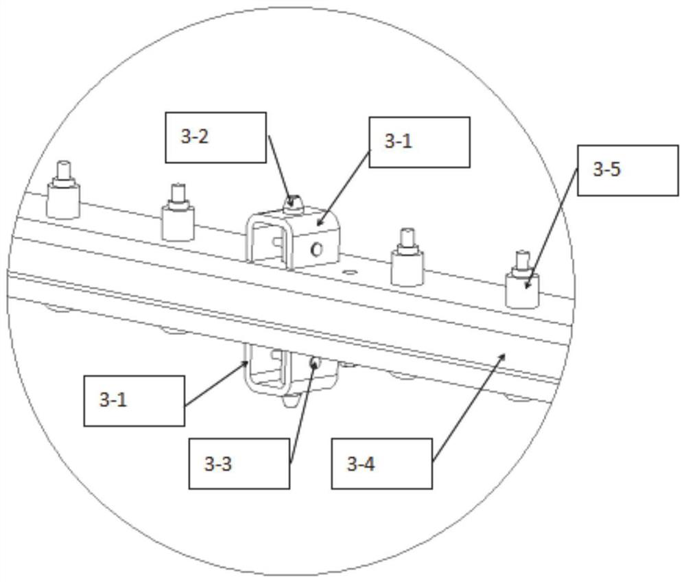
[0045] Further, the positioning connection structure includes maintenance-free high-strength fasteners, and the sheets are connected by maintenance-free high-strength fasteners;

[0046] Further, the positioning connection structure includes arc-shaped steel plates, split-t...

Embodiment 2

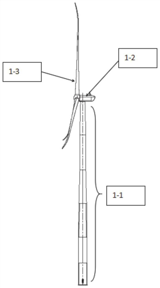
[0056] Such as figure 1 As shown, the present disclosure provides a wind power generating set, including the sheet-mounted tower as described in the above embodiments, and also includes a nacelle system and a wind turbine system connected to the sheet-mounted tower;

[0057] The wind turbine system and nacelle system are customized according to the needs of the wind farm project to meet the power generation requirements of the wind farm project. The chip-mounted tower is designed according to the load data, height requirements, transportation requirements and other conditions of the wind farm project, and the towers exceeding the transportation size limit are determined to be chip-mounted to meet the safety and reliability design requirements of the unit, and further meet the shipping requirements.

[0058] Specifically, as one of the implementations, the wind turbine system includes a hub, blades and a drive shaft, the hub is connected to the blades; one end of the drive sha...

Embodiment 3

[0061] A method for manufacturing a sheet-mounted tower, comprising:

[0062] Obtain a steel plate with a set size, and form a cylindrical structure after processing;

[0063] Install the flanges at both ends of the cylindrical structure to form a piece-mounted barrel section;

[0064] Carry out the cutting of the set line for the piece-packed barrel section, and cut it into multiple pieces;

[0065] A plurality of pieces are assembled to form a piece-mounted tower.

[0066] Specifically, after the steel plate is cut according to the size, use the steel plate rolling equipment to roll the steel plate into a circle;

[0067] Further, the butt joints of the coiled steel plates are automatically welded by submerged arc to form segments;

[0068] Further, use the steel plate rolling equipment to correct the roundness of the segment;

[0069] Further, the segments are butt-welded in a circumferential direction to form a cylindrical structure;

[0070] Further, using fixed tool...


PUM


Abstract

The invention provides a sheet-mounted tower, a manufacturing and mounting method and a wind turbine generator. The sheet-mounted tower comprises at least one sheet-mounted shell ring, the sheet-mounted shell ring comprises a plurality of sheet bodies and positioning connecting structures, and the plurality of sheet bodies are connected through the positioning connecting structures; and a plurality of sheet-mounted shell rings are arranged, and the sheet-mounted shell rings are connected through flanges. The tower of which the diameter exceeds the transportation size requirement is longitudinally cut to form three or more parts, so that the transportation size requirement is met, the problem that the connection structure of tower sheet bodies is unreasonable in arrangement is solved, and the problems of inaccurate positioning and difficult connection during sheet body assembly, inclination and non-uniform stress of a tower drum caused by sheet body dislocation, damage to electrical equipment caused by gap water leakage, tedious installation caused by diversity of accessories and the like are solved.

Description

technical field [0001] The present disclosure relates to an application field of wind power generation equipment, in particular to a sheet-mounted tower, a manufacturing and installation method, and a wind turbine, specifically a sheet-mounted tower, an accessory module, a manufacturing and installation method, and a wind turbine. Background technique [0002] The statements in this section merely provide background information related to the present disclosure and may not necessarily constitute prior art. [0003] The tower is an important component system of the wind turbine, used to support the upper nacelle system and the wind wheel system. With the rapid development of land-based high-power units, wind resources are continuously developed and utilized. In the case of relatively stable wind speeds and relatively high annual average wind speeds within the safety level of wind turbines, there are fewer and fewer wind areas, and areas with large wind shear changes are not ...

Claims


Application Information

Patent Timeline
IPC IPC(8): F03D13/20F03D80/80F03D13/10B23P15/00
CPCF03D13/20F03D80/88F03D13/10B23P15/00Y02E10/72Y02P70/50Y02E10/728
Inventor 焦守雷张国伟王子月赵爱珑
Owner CRRC WIND POWER(SHANDONG) CO LTD
Why Eureka
Try Eureka