
Dual-frequency dual-polarization Fabry-Perot resonant cavity antenna

A resonant cavity antenna and dual-polarization technology, applied in resonant antennas, antennas, antenna arrays, etc., can solve the problems that the working frequency cannot be adjusted independently, the structure of the frequency selection surface unit is complex, and the polarization form is single, so as to improve the radiation direction Figure, electromagnetic wave stabilization, the effect of realizing linear polarization and circular polarization

Active Publication Date: 2021-06-01
XIDIAN UNIV
View PDF12 Cites 7 Cited by
  • Summary
  • Abstract
  • Description
  • Claims
  • Application Information

AI Technical Summary

Problems solved by technology

For the currently existing dual-frequency dual circularly polarized Fabry-Perot resonant cavity antennas, most of them adopt dual-frequency line-polarized feeds and frequency-selective surfaces with dual-frequency dual circularly polarized characteristics, but for this type of antenna, there are frequency selection The surface unit structure is relatively complex, the operating frequency cannot be adjusted independently, and the polarization form is single.

Method used


Image

  • Dual-frequency dual-polarization Fabry-Perot resonant cavity antenna
  • Dual-frequency dual-polarization Fabry-Perot resonant cavity antenna
  • Dual-frequency dual-polarization Fabry-Perot resonant cavity antenna

Examples


Embodiment Construction

[0030] Below in conjunction with accompanying drawing, specific embodiment of the present invention and effect are described in further detail:

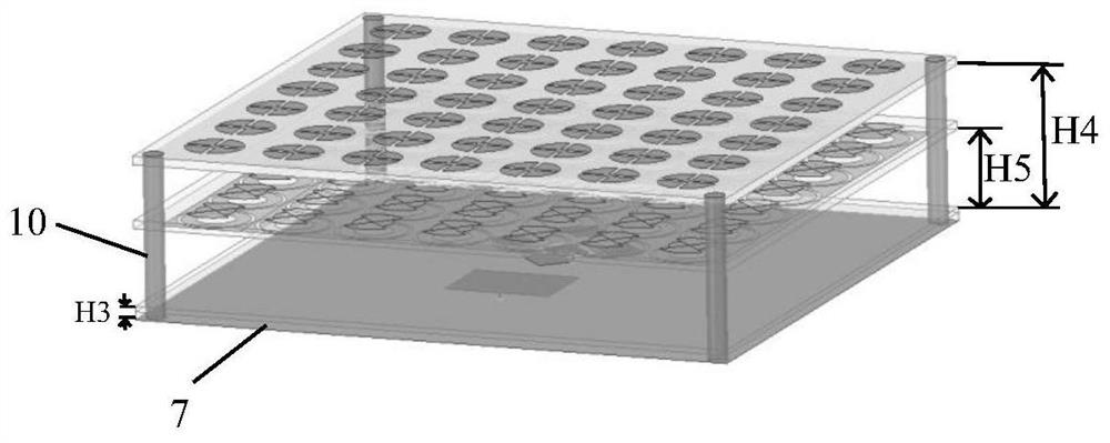
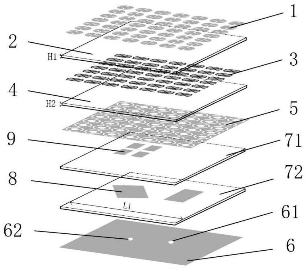
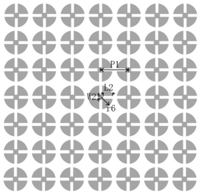
[0031] refer to figure 1 with figure 2 : The dual-frequency dual-polarization Fabry-Perot resonant cavity antenna of this example includes a part of the upper reflective surface 1, an upper dielectric substrate 2, a part of the middle reflective surface 3, an intermediate layer of dielectric substrate 4, a part of the lower reflective surface 5, and a metal floor 6. The bottom dielectric substrate 7 , the parasitic patch 8 , the parasitic rectangular patch array 9 , and the support 10 , the upper dielectric substrate 2 , the middle dielectric substrate 4 and the bottom dielectric substrate 7 are fixed as one by the support 10 . in:

[0032] The part of the upper reflective surface 1 is located on the upper part of the upper dielectric substrate 2, and the two form an upper part of the reflective surface structure for low-frequency...


PUM

PropertyMeasurementUnit
lengthaaaaaaaaaa
thicknessaaaaaaaaaa
thicknessaaaaaaaaaa

Abstract

The invention discloses a dual-frequency dual-polarization Fabry-Perot resonant cavity antenna. The antenna comprises an upper dielectric substrate, a middle dielectric substrate and a lower dielectric substrate (2, 4 and 7) which are fixed into a whole through low-dielectric-constant nylon columns (10). The upper surface of the upper-layer dielectric substrate is provided with an upper partial reflection surface (1), and the upper-layer dielectric substrate and the partial upper reflection surface form an upper-layer partial reflection surface structure; a middle partial reflection surface (3) and a lower partial reflection surface (5) are respectively arranged above and below the middle dielectric substrate, and the middle partial reflection surface, the lower partial reflection surface and the middle dielectric substrate form a lower-layer partial reflection surface structure; and the bottom dielectric substrate comprises two layers of dielectric plates (71 and 72), a parasitic patch (8) is arranged between the two layers, a metal floor (6) is arranged on the lower surface of the first-layer dielectric plate, a parasitic rectangular patch array (9) is arranged on the upper surface of the second-layer dielectric plate, and the two dielectric plates, the parasitic patch, the metal floor and the parasitic rectangular patch array form a feed source structure. According to the invention, linear polarization and circular polarization can be realized at the same time, channel capacity is improved, signal attenuation is reduced, and the antenna can be used for astronomical detection and satellite communication systems.

Description

technical field [0001] The invention belongs to the technical field of antennas, in particular to a Fabry-Perot resonant cavity antenna, which can be used for astronomical exploration and satellite communication. Background technique [0002] The Fabry-Perot resonant cavity was first produced in 1897 and was jointly invented by Frenchmen Charles Fabry and Alfred Perot. The Fabry-Perot resonant cavity antenna loads a frequency selective surface above the traditional microstrip antenna, and uses the microstrip feed source and the frequency selective surface to form a cavity, so that the energy of the feed source oscillates multiple times in the cavity, and finally all radiates out of the cavity. The high-gain performance of the Fabry-Perot resonant cavity antenna makes it of great application value in the fields of astronomical exploration and satellite communication, and has always been an important research direction for microwave and antenna scholars. [0003] The dual-fre...

Claims


Application Information

Patent Timeline
Patent Type & Authority Applications(China)
IPC IPC(8): H01Q15/14H01Q21/06H01Q21/00H01Q1/36H01Q1/50H01Q9/04
CPCH01Q15/145H01Q21/065H01Q21/0031H01Q1/50H01Q1/36H01Q9/04
Inventor 赵钢徐贺罗传威周世国陈官韬姜旭鸿李威宗
Owner XIDIAN UNIV
Learn More