Eureka AIR delivers breakthrough ideas for toughest innovation challenges, trusted by R&D personnel around the world.

Flame-retardant fireproof power wiring bus duct

A technology for power wiring and bus ducts, applied in the directions of fully enclosed busbar devices, semi-enclosed busbar devices, circuits, etc., can solve the problems of loose connection of adjacent busbar ducts, wall damage, disconnection of busbar duct lines, etc. Avoid shaking, reduce damage, and hold firmly

Inactive Publication Date: 2021-06-01
武汉冬官尚科技有限公司
View PDF0 Cites 4 Cited by
  • Summary
  • Abstract
  • Description
  • Claims
  • Application Information

AI Technical Summary

Problems solved by technology

[0003] At present, the following problems exist in the use of flame-retardant and fire-resistant power wiring bus ducts: a. Most of the traditional bus ducts are directly fixed on the wall during installation, and the distribution wiring according to the wall needs to be carried out on the wall. A large number of drilling holes will cause certain damage to the wall and affect the appearance. At the same time, this method will make the disassembly and assembly of the busway inconvenient, resulting in inconvenience in the later maintenance or replacement of parts; b. the current existing busway All bus ducts are assembled first, and multiple bus ducts are connected and then fixed on the wall. In this process, the connection between adjacent bus ducts is likely to be loosened, resulting in the disconnection of the bus duct lines, which cannot Troubleshooting while troubleshooting cause and location of faults

Method used


Image

  • Flame-retardant fireproof power wiring bus duct
  • Flame-retardant fireproof power wiring bus duct
  • Flame-retardant fireproof power wiring bus duct

Examples


Embodiment Construction

[0030] Embodiments of the present invention will be described below with reference to the drawings. In the process, in order to ensure the clarity and convenience of illustration, we may exaggerate the width of the lines or the size of the constituent elements in the diagram.

[0031] In addition, the following terms are defined based on the functions in the present invention, and may be different according to the user's or operator's intention or practice. Therefore, these terms are defined based on the entire content of this specification.

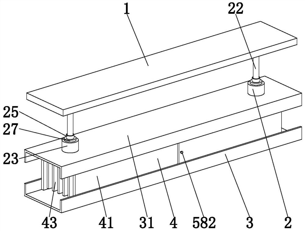
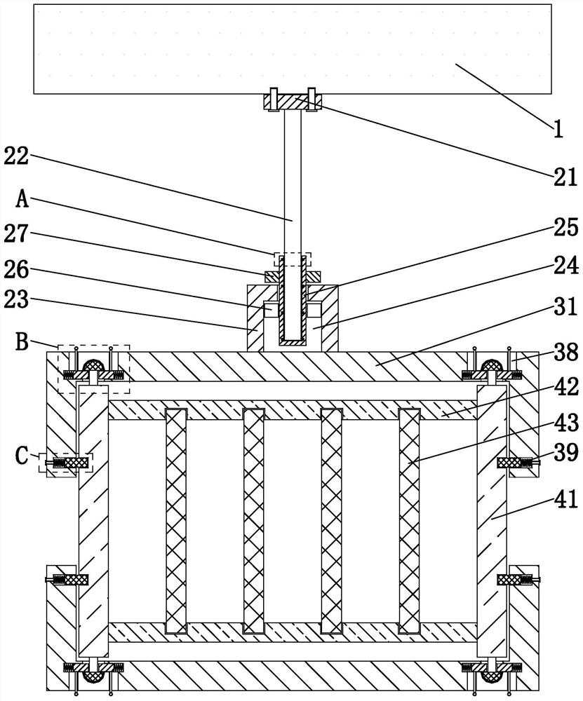
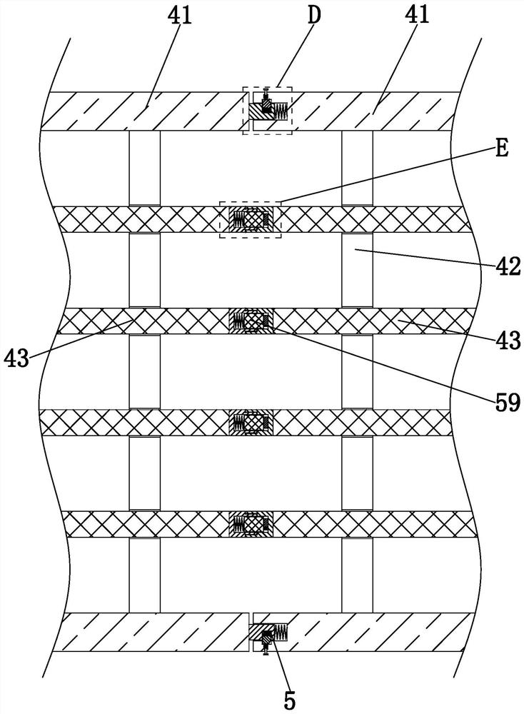
[0032] Such as Figure 1 to Figure 8 As shown, a flame-retardant and fire-resistant power wiring busway includes a wall 1, a suspension mechanism 2, an outer card mechanism 3, a conductor assembly 4 and a docking mechanism 5, and two adjacent conductor assemblies 4 are connected to each other through the docking mechanism 5. Connected, the conductor assembly 4 is symmetrically slid up and down with an outer card mechanism 3, and the ou...


PUM


Abstract

The invention provides a flame-retardant fireproof power wiring bus duct. The flame-retardant fireproof power wiring bus duct comprises a wall body, a suspension mechanism, an outer clamping mechanism, a conductor assembly and a butt joint mechanism. The flame-retardant fireproof power wiring bus duct can solve the following problems existing in the use process of the flame-retardant fireproof power wiring bus duct: a, most of traditional bus ducts are directly fixed on a wall body in the installation process, wiring is distributed according to the wall body, and a large amount of holes need to be drilled in the wall body, so that the wall body is damaged to a certain extent, the appearance is influenced, meanwhile, the bus duct is inconvenient to disassemble and assemble, and the operation is inconvenient during later maintenance or part replacement; and b, a plurality of bus ducts are connected and then fixed on a wall body after the bus ducts are assembled in the prior art, so that the connection between the adjacent bus ducts is easy to loosen in the process, the bus duct lines are disconnected and cannot be electrified, and troubles are caused when fault reasons and positions are troubleshot at the same time.

Description

technical field [0001] The invention relates to the technical field of bus ducts, in particular to a flame-retardant and fireproof power wiring bus duct. Background technique [0002] The busway is a closed metal device composed of copper and aluminum busbar columns, which is used to distribute large power to various components of the decentralized system. It has increasingly replaced wires and cables in indoor low-voltage power transmission trunk line projects. The characteristics of the bus duct are series matching, commercial production, small size, large capacity, short design and construction period, non-combustible, safe and reliable, and long service life. Busway products are suitable for three-phase four-wire and three-phase five-wire power supply and distribution system projects with AC 50Hz, rated voltage 380V, and rated current 250A-6300A. [0003] At present, the following problems exist in the use of flame-retardant and fire-resistant power wiring bus ducts: a...

Claims


Application Information

Patent Timeline
IPC IPC(8): H01R13/639H02G5/04H02G5/06
CPCH02G5/04H02G5/06H01R13/639
Inventor 王杰
Owner 武汉冬官尚科技有限公司
Why Eureka
Eureka Blog
Learn More