Automatic resonance energy balancing method and used device
A technology of automatic balance and energy device, which is applied in the direction of output power conversion device, adjustment of electrical variables, instruments, etc., to achieve the effect of precise control of output current
- Summary
- Abstract
- Description
- Claims
- Application Information
AI Technical Summary
Problems solved by technology
Method used
Image
Examples
Embodiment 1
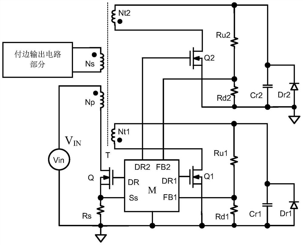
[0063] Embodiment 1: a kind of automatic balance resonance energy device, such as image 3 Shown:
[0064] Including functional module M, output isolation transformer, MOS tube Q1, MOS tube Q2, primary side MOS tube Q, two sets of resonant reset circuits;
[0065] The output isolation transformer includes a primary winding Np, a secondary winding Ns, a reset winding Nt1, and a reset winding Nt2, and these 4 windings are wound on the same magnetic core;
[0066] A set of resonant reset circuit is: resistor Ru1 and resistor Rd1 are first connected in series, then connected in parallel with resonant capacitor Cr1 and diode Dr1, and resistor Rd1 is grounded; resistor Ru1 is connected to the non-identical terminal of reset winding Nt1;
[0067] Another set of resonant reset circuit is: resistor Ru2 and resistor Rd2 are first connected in series, and then connected in parallel with resonant capacitor Cr2 and diode Dr2, and resistor Rd2 is grounded; resistor Ru2 is connected to the ...
Embodiment 2
[0086] Embodiment 2, as Figure 4 shown.
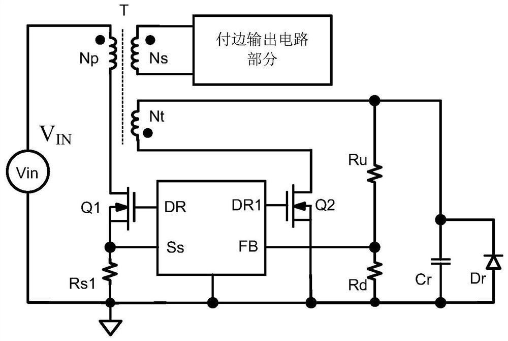
[0087] Corresponding to Example 1 image 3 than, eliminating the need for a resonant reset winding. The function module M controls the MOS transistor Q1 or MOS transistor Q2 to turn on / off according to the internal system logic circuit and the feedback voltage FB (that is, the voltage waveform of the detection winding Nt) or the body diode current information of the MOS transistors Q1 and Q2; the MOS transistor Q1 Control the resonant reset network of the resonant capacitor Cr1; the MOS transistor Q2 controls the resonant reset network of the resonant capacitor Cr2. Resonant capacitance Cr1=Cr2.
[0088] Specifically:
[0089] Including functional module M, output isolation transformer, MOS tube Q1, MOS tube Q2, primary side MOS tube Q, and a set of resonant reset circuit;
[0090] The output isolation transformer includes a primary winding Np, a secondary winding Ns, and a reset winding Nt;
[0091] The resonant reset circuit i...
Embodiment 3
[0105] Embodiment 3, corresponding image 3 The resonant reset circuit is completed on the secondary side of the isolation transformer, such as Figure 6 shown. details as follows:
[0106] Compared with embodiment 1, the difference points are:
[0107] Figure 6 The resonant reset works with the image 3 It is exactly the same, just because the resonance reset is controlled on the secondary side of the isolation transformer, so the conduction of the MOS transistor Q on the primary side of the isolation transformer needs to be driven by the functional module M on the secondary side of the isolation transformer via a coupling pulse transformer or two coupling capacitors. According to the output information of the functional module M received from the driving pulse transmitted by the coupling pulse transformer or two coupling capacitors, the functional module M1 requires the conduction and cut-off information of the MOS tube on the primary side of the isolation transformer, ...
PUM
 Abstract
Description
Claims
Application Information
 - R&D
- Intellectual Property
- Life Sciences
- Materials
- Tech Scout
- Unparalleled Data Quality
- Higher Quality Content
- 60% Fewer Hallucinations
Browse by: Latest US Patents, China's latest patents, Technical Efficacy Thesaurus, Application Domain, Technology Topic, Popular Technical Reports.
© 2025 PatSnap. All rights reserved.Legal|Privacy policy|Modern Slavery Act Transparency Statement|Sitemap|About US| Contact US: help@patsnap.com


