Environment-friendly building construction waste recycling device

A technology for building construction and recycling devices, which is applied in construction waste recycling, furniture waste recycling, recycling technology, etc., and can solve problems such as screening, inability to fully classify construction waste, and low efficiency of waste classification and recycling

Inactive Publication Date: 2021-06-04
YELLOW RIVER CONSERVANCY TECHN INST
View PDF7 Cites 4 Cited by
  • Summary
  • Abstract
  • Description
  • Claims
  • Application Information

AI Technical Summary

Problems solved by technology

[0005] Aiming at the above problems, the present invention provides an environment-friendly construction waste recycling device, which solves the problems mentioned in the above-mentioned background technology that the construction waste cannot be fully classified, the efficiency of waste classification and recovery is low, and it cannot be used for rod-shaped waste. The problem of screening bamboo and wood

Method used


Image

  • Environment-friendly building construction waste recycling device
  • Environment-friendly building construction waste recycling device
  • Environment-friendly building construction waste recycling device

Examples


Embodiment 1

[0033] Embodiment 1, an environment-friendly building construction waste recovery device, comprising a frame 1, characterized in that two sets of screens 2 are vertically slidably connected to the channel in the frame 1, and the two sets of screens 2 are vertically connected to each other. Arranged at intervals, the distance between the two groups of screens 2 should meet the length of the rod-shaped waste as far as possible, so that the rod-shaped waste can pass through the upper screen 2 and then enter the lower screen 2. The screen 2 There are multiple groups of rectangular slots 3 arranged at intervals on the top, and the slots 3 on the two groups of screens 2 are arranged at ninety degrees. Block stones, concrete clots can leak from the elongated holes 3, and the purpose of setting two groups of screens 2 is to allow these finely broken stones, concrete blocks, and iron nails to pass through the two groups of screens 2 smoothly. After the long holes 3 of the wooden strips...

Embodiment 2

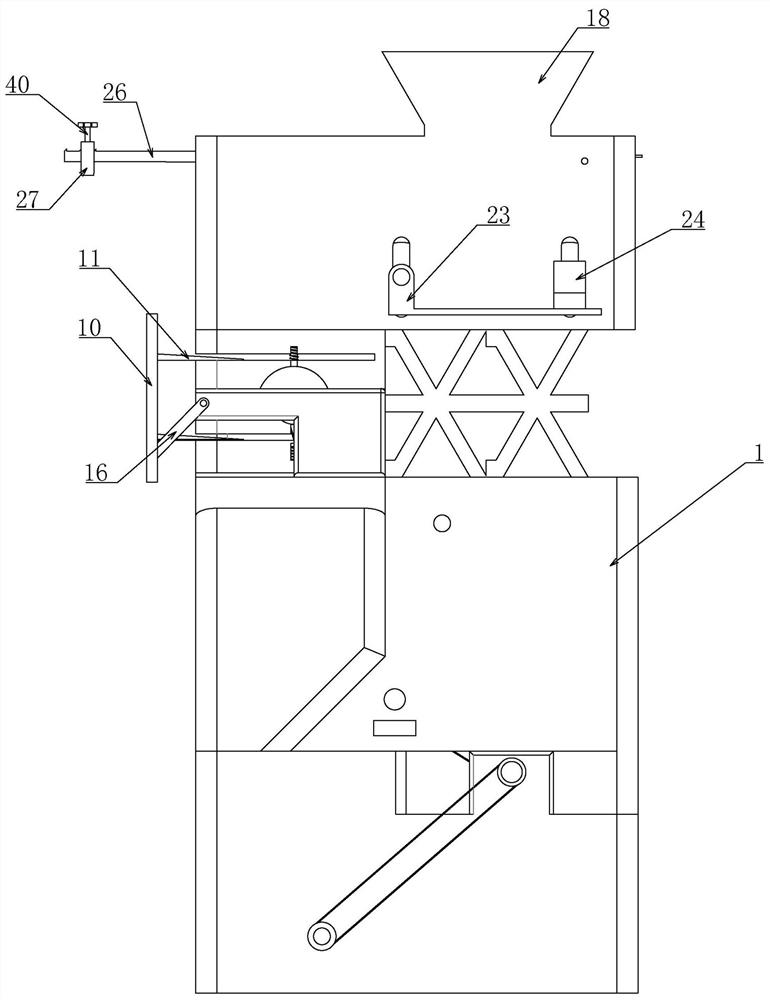
[0035] Embodiment 2. On the basis of Embodiment 1, the reciprocating sweeping device includes a U-shaped bar 10 transversely connected to the frame 1, and two poles of the U-shaped bar 10 are respectively transversely connected with a surface The oblique baffle plate 11, the U-shaped bar 10 is laterally clamped on the frame 1 through two sets of baffle plates 11, the baffle plate 11 is sandwiched between the screen 2 and the frame 1, and at this position The screen 2 is driven to the extreme position by the cam 6, and the lower end of the baffle plate 11 is attached to the screen 2 on the corresponding side, and also includes a first gear 12 coaxially installed on the transmission shaft 5. The first gear 12 is meshed with the second gear 13 that is rotatably connected to the frame 1. The cam 6 is formed by butting two groups of semicircular plates with different radii. The large semicircular plate is the radius of the small semicircular plate. twice, and the radius of the firs...

Embodiment 3

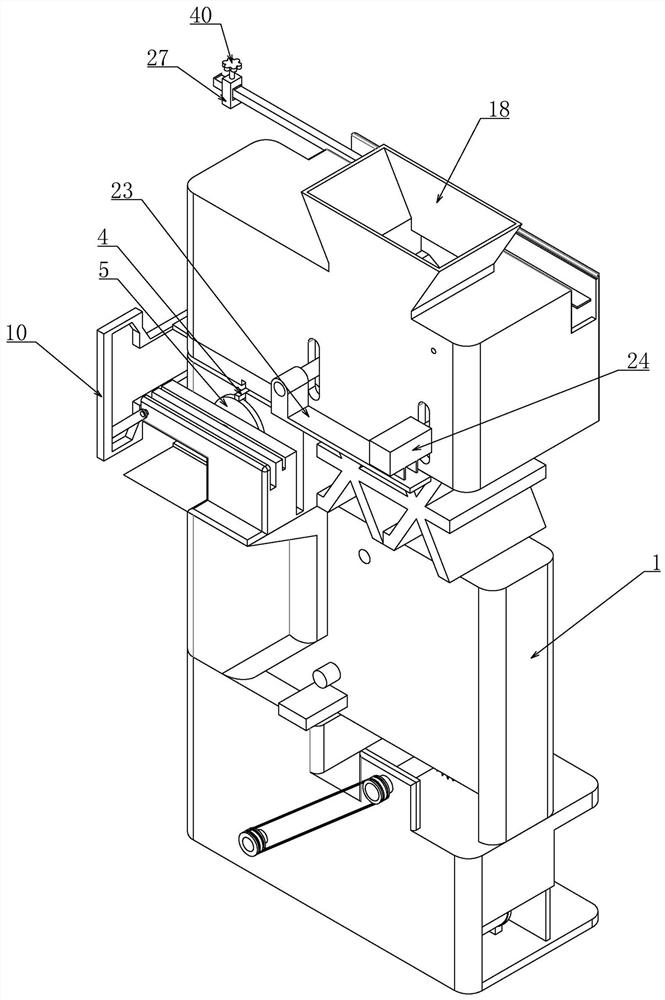
[0037] Embodiment 3, on the basis of Embodiment 1, the described uniform feeding device includes a feeding hopper 18 installed on the upper end of the frame 1, the feeding hopper 18 is used to hold bulk materials, and the described feeding hopper 18 The left end of the lower end is connected with a long vertical plate 19, and the right end is connected with a short vertical plate 20. The frame 1 is vertically connected with two groups of first pulleys 21 placed below the lower hopper. There is a vertical strip-shaped hole structure, and the rotating shaft of the first pulley 21 is inserted into the strip-shaped hole-shaped structure, so that it can only move along the vertical direction. A first belt 22 is provided, wherein one end of the rotating shaft of one set of first pulleys 21 is connected to the connection plate 23, and one end of the rotating shaft of the other set of first pulleys 21 is connected with the output shaft of the first motor 24 installed on the connecting ...


PUM


Abstract

The invention relates to an environment-friendly building construction waste recycling device. Two sets of screens which are used in a matched manner are adopted in the device, long-strip-shaped holes used for leaking materials are formed in the two sets of screens, and the long-strip-shaped holes in the two sets of screens are perpendicular to each other, so that bar-shaped bamboos, wood, iron bars and the like cannot pass through the second layer of screen even if passing through the first layer of screen; the vibrating effect on the screens is achieved through cooperation of a cam and a reset spring, materials are prevented from being clamped at the positions of the long-strip-shaped holes, the cam drives a reciprocating driving device to sweep and concentrate the bar-shaped materials on the screens, and meanwhile, the number of the materials entering the screens is evenly controlled through the self-adaptive adjusting function of the weight in the even feeding process; and a crushing device and an iron material adsorption device are arranged at the lower end of a rack, so that crushing and classification treatment work of the materials is achieved. The environment-friendly building construction waste recycling device is high in building construction waste treatment efficiency, capable of recycling various different types of waste, high in practicability and suitable for application and popularization.

Description

technical field [0001] The invention belongs to the technical field of garbage recovery equipment, in particular to an environment-friendly building construction garbage recovery device. Background technique [0002] Construction waste refers to the general designation of muck, waste concrete, waste masonry and other waste generated in the production activities of people engaged in demolition, construction, decoration, repair and other construction industries. Classified by source, construction waste can be divided into engineering dregs, decoration waste, demolition waste, engineering mud, etc.; classified by composition, construction waste can be divided into dregs, concrete blocks, [1] Broken stones, broken bricks and tiles, waste mortar, mud, asphalt blocks, waste plastics, waste metal, waste bamboo and wood, etc. [0003] In order to achieve the effect of environmental protection, these construction wastes need to be recycled for secondary use. The purpose of recycling...

Claims


Application Information

Patent Timeline
Patent Type & Authority Applications(China)
IPC IPC(8): B09B3/00B07B1/34B07B1/42B07B1/46B03C1/30B03C1/18B02C1/04
CPCB09B3/00B07B1/343B07B1/42B07B1/4609B03C1/30B03C1/18B02C1/04B07B2201/04B02C2201/06Y02W30/58Y02W30/78
Inventor 孙玉龙程格格胡畔王朦诗张斯琪郭俊超冯向波
Owner YELLOW RIVER CONSERVANCY TECHN INST
Why Eureka
Try Eureka