

Far ultraviolet disinfection lighting device, control method and equipment
A technology for lighting devices and lighting equipment, applied in lighting devices, lighting devices, independent lighting devices, etc., can solve problems such as damage to eyes and skin, electro-optic ophthalmia, eye trauma and skin burns
- Summary
- Abstract
- Description
- Claims
- Application Information
AI Technical Summary
Problems solved by technology
Method used
Image

Examples
Embodiment 1
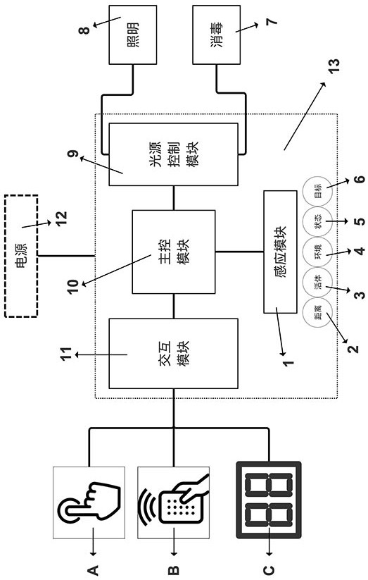
[0050] Such as figure 1 Shown is a functional block diagram of a disinfection lighting device according to an embodiment of the present invention. In this embodiment, the control device 13 includes a main control module 10, an interaction module 11, a sensing module 1 and a light source control module 9 connected to each other.
[0051] Further, the illuminating lamp 8 and the sterilizer 7 are respectively connected to the light source control module 9, and the light source control module 9 has two parts inside, namely a high-voltage part and a low-voltage part, the high-voltage part is responsible for driving and controlling the sterilizer, and the low-voltage part is responsible for driving the illuminating lamp .
[0052] Optionally, heat dissipation devices, such as fans or cooling fins, can also be provided for the illuminating lamp 8 and the sterilizer 7 .
[0053] Further, the sensing module 1 includes distance detection 2, living body detection 3, environmental paramete...
Embodiment 2
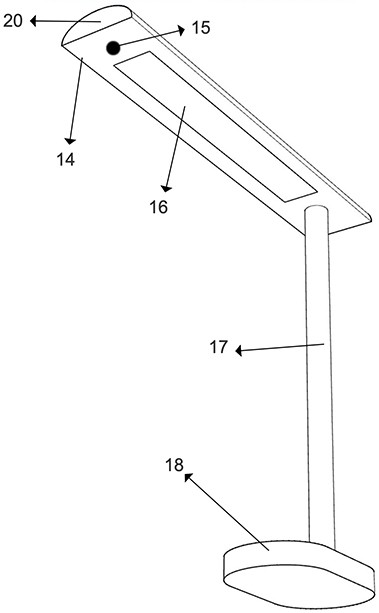
[0069] figure 2 It shows a schematic diagram of a disinfection lighting device of the present invention, which is a floor lamp or a table lamp. The working principle of this embodiment is roughly the same as that of Embodiment 1. Some parameters of the sensing module, such as distance detection, are selected as input, and a new structure is adopted design. In this embodiment, the induction module 15, the illuminating lamp 14 and the sterilizer 16 are arranged inside the same housing structure 20, and the ultraviolet light outlet and the illumination light outlet are on the same plane, and the output direction is the same, which is beneficial to carry out while illuminating. The disinfection work is also convenient to reduce the volume and cost. The base 18 is provided with a power supply interface and a control device, and the shell structure 20 is connected to the base 18 through the connector 17, and the wiring connection inside the connector 17 is respectively connected t...
Embodiment 3
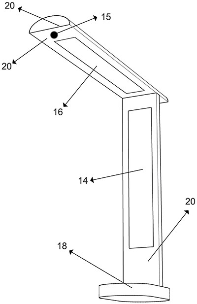
[0071] image 3 It is a schematic diagram of a device for separating the disinfection and lighting shells of the present invention. The difference between this embodiment and the second embodiment is that the shell structure 20 adopts a separate type, and the sterilizer 16 is responsible for irradiating and disinfecting in the vertical direction. Through the induction module 15, the The irradiation dose and time are controlled, while the illuminating lamp 14 performs irradiation in the horizontal direction, and the rest of the effects are the same as in the second embodiment, but it is an optimized design to meet different application scenarios and cost considerations, and the sterilizer 16 can be combined with the The positions of the illuminating lamps 14 are exchanged to meet the usage requirements of different application scenarios.
PUM
 Abstract
Description
Claims
Application Information