Permanent magnet excitation active and reactive power control system

A technology of power control and permanent magnet, which is applied in the direction of reducing/preventing power oscillation, harmonic reduction device, AC network load balancing, etc., and can solve problems such as inability to adjust active power, inability to perform primary frequency modulation, and low reliability of synchronous condensers , to achieve the effect of good application prospect, light weight and high reliability

Active Publication Date: 2021-06-04
HARBIN INST OF TECH
View PDF7 Cites 2 Cited by
  • Summary
  • Abstract
  • Description
  • Claims
  • Application Information

AI Technical Summary

Problems solved by technology

[0010]The purpose of the present invention is to solve the problems of low reliability of existing syn...

Method used


Image

  • Permanent magnet excitation active and reactive power control system
  • Permanent magnet excitation active and reactive power control system

Examples


specific Embodiment approach 1

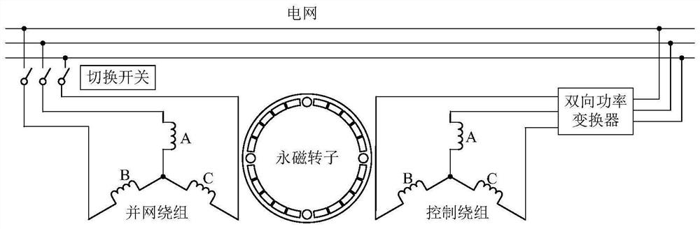
[0060] Specific implementation mode one: combine figure 1 Describe this embodiment, the permanent magnet excitation active and reactive power control system described in this embodiment, the system includes a double-winding permanent magnet synchronous motor, an inertia flywheel, a bidirectional power converter, a sensor, a controller, and a switch;

[0061] The double-winding permanent magnet synchronous motor has a radial magnetic field or an axial magnetic field structure. The double-winding permanent magnet synchronous motor includes a stator structure and a rotor structure, and there is an air gap between the stator structure and the rotor structure;

[0062] The stator structure includes stator core, grid-connected winding and control winding, the stator core is slotted, the grid-connected winding and control winding are embedded in the slot, and the grid-connected winding and control winding are multi-phase symmetrical AC windings;

[0063] The grid-connected winding is...

specific Embodiment approach 2

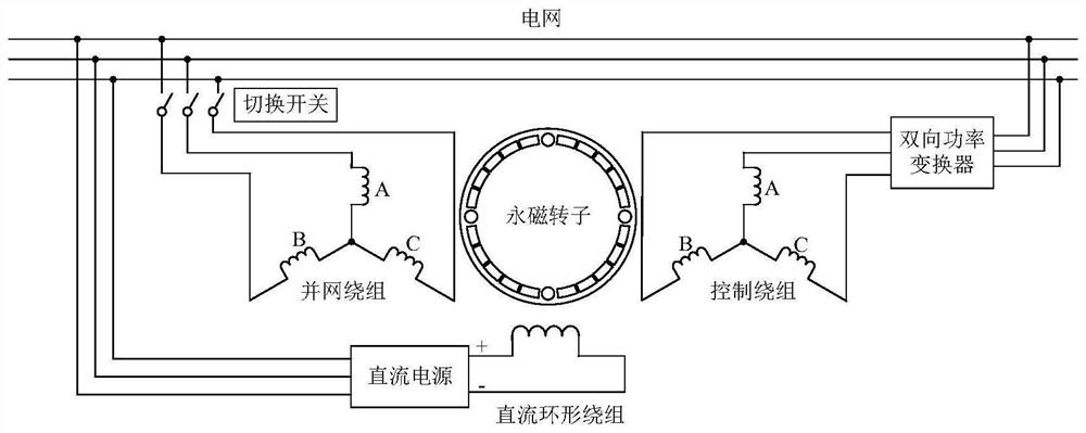
[0069] Embodiment 2: This embodiment is the permanent magnet excitation active and reactive power control system described in Embodiment 1. The stator structure of the permanent magnet synchronous motor includes a stator core, a grid-connected winding and a control Winding, the rotor structure includes 2 rotors;

[0070] The two rotors are located on both sides of the stator core in the axial direction, and the two rotors are mechanically connected together;

[0071] The stator core is circular, and there are radial slots on the two axial air gap surfaces of the circular stator core. The slots are evenly distributed along the circumferential direction. in the slots on both sides;

[0072] Each rotor includes a rotor core and permanent magnets, and the magnetization directions of the corresponding permanent magnets on the two rotors are the same.

[0073] In this embodiment, the magnetization directions of the permanent magnets at corresponding positions on the two rotors are...

specific Embodiment approach 3

[0074] Embodiment 3: This embodiment is the permanent magnet excitation active and reactive power control system described in Embodiment 1. The double-winding permanent magnet synchronous motor is an axial magnetic field structure, and the double-winding permanent magnet synchronous motor is an axial magnetic field. Structure, the stator structure of the double-winding permanent magnet synchronous motor includes 2 stator cores, 1 grid-connected winding and 1 control winding, and the rotor structure includes 1 rotor;

[0075] The two stator cores are located on both sides of the rotor in the axial direction. The two stator cores are circular. There are radial slots on the axial air gap surface of each circular stator core. The slots are evenly distributed along the circumferential direction. The grid-connected winding and the control winding are respectively embedded in two air-gap side slots of the stator core, one stator core and one grid-connected winding form a stator, and t...


PUM


Abstract

The invention provides a permanent magnet excitation active and reactive power control system, and belongs to the field of motors. The objective of the invention is to solve the problems of low reliability, incapability of adjusting active power and incapability of performing primary frequency modulation of the existing synchronous phase modifier. The invention relates to a permanent magnet excitation active and reactive power control system, which adopts a permanent magnet excitation synchronous motor, has no rotor excitation loss, and is simple in rotor structure, high in reliability and long in service life. The electromotive force of the grid-connected winding of the motor is detected through the sensor, meanwhile, the controller adjusts and controls the winding output current, the phase and the phase sequence of the electromotive force of the grid-connected winding are made to be the same as those of the corresponding phase voltage of the power grid, the change-over switch is closed, and the grid-connected winding is connected with the power grid. The system is used for realizing active and reactive control.

Description

technical field [0001] The invention relates to a permanent magnet excitation active and reactive power control system, which belongs to the field of motors. Background technique [0002] With the rapid increase in the proportion of new energy output, the continuous increase in the scale of direct current transmission, and the widespread application of power electronics technology, the operating characteristics and mechanism of the power system have undergone profound changes. The "weak moment of inertia" of wind power and the "zero moment of inertia" of photovoltaics lead to a significant reduction in the equivalent moment of inertia of the power system, weakening of the frequency regulation capability, and a sharp increase in the risk of frequency instability under large-capacity disturbance events. At the same time, the electromechanical and electromagnetic transient processes are intertwined, the system stability is complex, the overvoltage problem at the large DC sendin...

Claims


Application Information

Patent Timeline
IPC IPC(8): H02J3/48H02J3/50H02J3/42H02J3/24H02J3/30H02J3/01
CPCH02J3/48H02J3/50H02J3/42H02J3/241H02J3/30H02J3/01Y02E60/16Y02E40/40
Inventor 寇宝泉张浩泉牟俊任
Owner HARBIN INST OF TECH
Why Eureka
Try Eureka