
Steel plate and manufacturing method thereof

A manufacturing method and technology for steel plates, which are applied in manufacturing tools, chemical instruments and methods, metal material coating processes, etc., can solve the problems of cracking, Zn intrusion, cracking of welded parts, etc., and achieve high ductility, high strength, Achieving a strengthening effect

Active Publication Date: 2022-06-21
JFE STEEL CORP
View PDF11 Cites 0 Cited by
  • Summary
  • Abstract
  • Description
  • Claims
  • Application Information

AI Technical Summary

Problems solved by technology

[0009] On the other hand, since a large amount of C and Si are added to this TRIP steel from the viewpoint of improving ductility, there is a problem that cracks tend to occur at welded parts
In the case of spot welding between Zn-plated steel sheets or between Zn-plated steel sheets and unplated cold-rolled steel sheets, Zn intrudes into the grain boundaries of the base metal to cause torsion near the weld nugget. cracked problem

Method used


Image

  • Steel plate and manufacturing method thereof
  • Steel plate and manufacturing method thereof
  • Steel plate and manufacturing method thereof

Examples


Embodiment 1

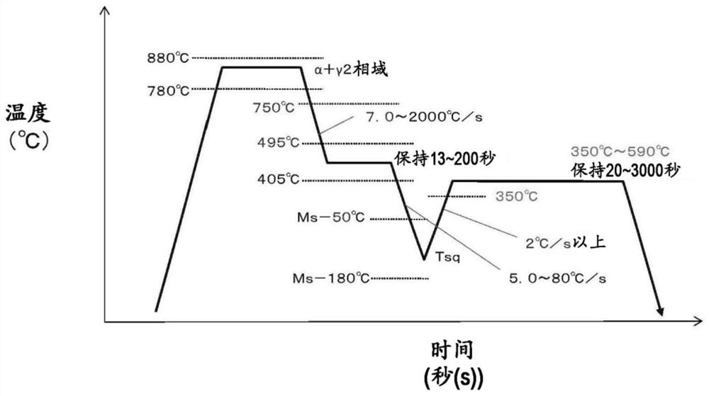
[0190] The steels having the component compositions shown in Table 1 were processed under the conditions shown in Table 2-1, and the steel sheets of the present invention and the steel sheets of the comparative examples were produced. The plate thickness of the steel plate is 1.4 mm. In addition, the conditions shown in Table 2-1 do not include zinc plating treatment.

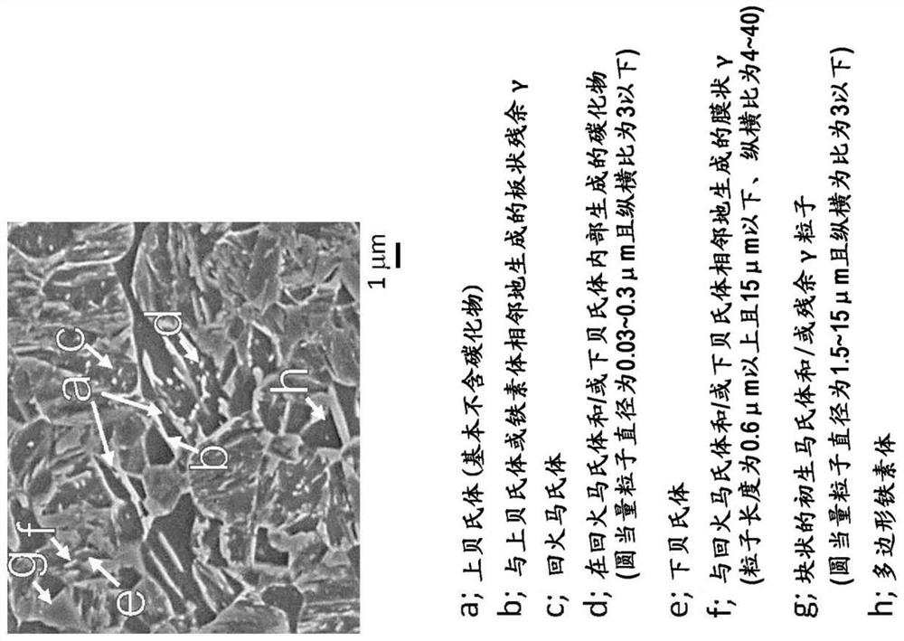
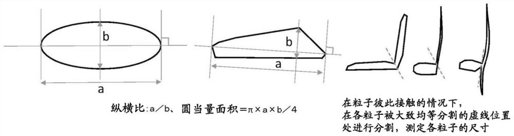
[0191] The measurement of the steel structure was carried out by the above-mentioned method. The measurement results are shown in Table 2-2.

[0192] A JIS No. 5 tensile test piece was collected from the produced steel sheet so that the direction perpendicular to the rolling direction became a tensile axis, and a tensile test (based on JIS Z2241) was carried out. TS and U.El are shown in Table 2-2.

[0193] In addition, the stretch flange formability was evaluated by the hole expansion test based on the specification of Japan Iron and Steel Federation Standard JFST1001. That is, after punching out a sample ...

Embodiment 2

[0205] The cold-rolled steel sheets having the component compositions shown in Table 3 were treated under the annealing conditions shown in Table 4-1, and the steel sheets of the present invention and the steel sheets of the comparative examples were produced. The plate thickness of the steel plate is 1.4 mm.

[0206] In addition, a part of steel sheets (cold-rolled steel sheets) were further subjected to hot-dip zinc plating treatment to prepare hot-dip zinc-coated steel sheets (GI). Here, the steel sheet is immersed in a zinc coating bath of 440° C. or higher and 500° C. or lower, molten zinc coating treatment is performed, and then, the coating adhesion amount is adjusted by gas wiping or the like. The molten zinc plating uses a zinc plating bath in which the amount of Al is 0.10% or more and 0.22% or less. Moreover, after the said hot-dip zinc-plating process, the alloying process of zinc plating was performed with respect to a part of hot-dip zinc-coated steel sheet, and...


PUM

PropertyMeasurementUnit
diameteraaaaaaaaaa
particle diameteraaaaaaaaaa
tensile strengthaaaaaaaaaa

Abstract

Provided are steel plates and manufacturing methods thereof. The steel of the present invention has a specific composition and a steel structure containing 6 to 90% of ferrite, 10 to 94% of upper bainite, and primary martensite in terms of area ratio. , tempered martensite, lower bainite, and residual γ in one or more structures, containing 3 to 15% of residual γ in terms of volume ratio; S C富集 0.1~5%, S C富集 is the total area ratio of the upper bainite region with a C concentration of 0.6-1.3% and the adjacent region is an upper bainite region with a short-axis width of 0.7-10 μm, an aspect ratio > 2.0, and a C concentration of 0.07% or less; S γBlock Below 5% (including 0%), S γBlock is the total area ratio of primary martensite with a circle equivalent particle diameter of 1.5 to 15 μm and an aspect ratio of 3 or less and / or residual γ particles with a circle equivalent particle diameter of 1.5 to 15 μm and an aspect ratio of 3 or less; the original γ on the surface The particle size is 2-12 μm.

Description

technical field [0001] The present invention relates to a steel sheet that can be suitably applied to press forming applications used in automobiles, home appliances, etc. through a press forming process, and to a method for producing the same. Background technique [0002] In recent years, due to the further increase in the demand for lightweight automobile bodies, the application of high-strength steel plates in the skeleton parts and sheet parts of automobiles has continued to develop. However, when a high-strength steel sheet having a tensile strength (TS) of 980 to 1180 MPa class is used for automobile parts, it is easy to generate press cracks due to a decrease in ductility and a decrease in stretch flange formability. Therefore, the formability of the above-mentioned high-strength steel sheets is expected to be better than conventional ones. [0003] From such a background, TRIP steel in which residual γ is dispersed in the microstructure of the steel sheet has been ...

Claims


Application Information

Patent Timeline
Patent Type & Authority Patents(China)
IPC IPC(8): C22C38/00C21D9/46C22C38/06C22C38/60
CPCC22C38/06C22C38/60C21D2211/005C21D2211/002C21D2211/008C21D2211/001C21D9/48C21D8/0426C21D8/0463C21D8/0436C21D8/0473C21D1/19C21D1/25C23C2/06C21D1/20C22C38/02C22C38/04C22C38/12C22C38/14C22C38/16C23C2/02C23C2/28C23C2/40Y02P10/20C23C2/0224C22C38/001C22C38/42C22C38/44C22C38/46C22C38/50C21D8/0226B21C47/02C21D8/0236C21D8/0273B32B15/013C21D6/005C21D6/008C21D8/0205C21D8/0263C21D9/46C22C38/002C22C38/08
Inventor 小野义彦高岛克利户畑润也松井洋一郎
Owner JFE STEEL CORP
Learn More