Casing material for power storage device, production method therefor, and power storage device
A manufacturing method and accumulator technology, which can be applied to hybrid capacitor electrodes, electrical components, battery pack components, etc., and can solve problems such as difficulty in coping with diverse shapes and limitations in light weight
- Summary
- Abstract
- Description
- Claims
- Application Information
AI Technical Summary
Problems solved by technology
Method used
Image
Examples
Embodiment 1 and comparative example 1
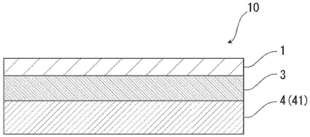
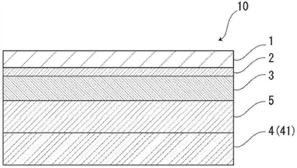
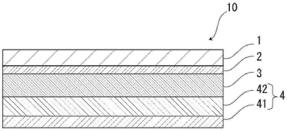
[0188] As the base material layer, a polyethylene terephthalate (PET) film (thickness 12 μm) and a stretched nylon (ONy) film (thickness 15 μm) were prepared, and a two-component polyurethane adhesive ( polyol compound and aromatic isocyanate-based compound) (3 μm) to adhere to the ONy film. Moreover, as a barrier layer, aluminum foil (JIS H4160:1994A8021H-O (thickness 40 micrometers)) was prepared. Next, a two-component urethane adhesive (polyol compound and aromatic isocyanate compound) was applied on one surface of the aluminum foil, and an adhesive layer (thickness 3 μm) was formed on the barrier layer. Next, after laminating the adhesive layer on the barrier layer and the base layer (ONy film side) by a dry lamination method, an aging treatment is performed to produce a laminate of the base layer / adhesive layer / barrier layer layer body. Both sides of the aluminum foil are chemically surface-treated. The chemical surface treatment of the aluminum foil was carried out by...
Embodiment 2 and comparative example 2
[0191]As the base material layer, a polyethylene terephthalate (PET) film (thickness 12 μm) and a stretched nylon (ONy) film (thickness 15 μm) were prepared, and a two-component polyurethane adhesive ( polyol compound and aromatic isocyanate-based compound) (3 μm) to adhere to the ONy film. Moreover, as a barrier layer, aluminum foil (JIS H4160:1994A8021H-O (thickness 40 micrometers)) was prepared. Next, a two-component urethane adhesive (polyol compound and aromatic isocyanate compound) was applied on one surface of the aluminum foil, and an adhesive layer (thickness 3 μm) was formed on the barrier layer. Next, after laminating the adhesive layer on the barrier layer and the base layer (ONy film side) by a dry lamination method, an aging treatment is performed to produce a laminate of the base layer / adhesive layer / barrier layer layer body. Both sides of the aluminum foil are chemically surface-treated. The chemical surface treatment of the aluminum foil was carried out by ...
Embodiment 3
[0194] As the base material layer, instead of the laminate of a polyethylene terephthalate (PET) film (thickness 12 μm) and a stretched nylon (ONy) film (thickness 15 μm), polyethylene terephthalate was used (PET) film (thickness: 25 μm), except that it was carried out in the same manner as in Example 1 to obtain base material layer (thickness: 25 μm) / adhesive layer (3 μm) / barrier layer (40 μm) / adhesive layer (20 μm) / The exterior material for electrical storage devices in which the 2nd heat-fusible resin layer (50 micrometers) / the 1st heat-fusible resin layer (10 micrometers) were laminated|stacked in this order.
PUM
| Property | Measurement | Unit |
|---|---|---|
| thickness | aaaaa | aaaaa |
| thickness | aaaaa | aaaaa |
| particle size | aaaaa | aaaaa |
Abstract
Description
Claims
Application Information
 - R&D
- Intellectual Property
- Life Sciences
- Materials
- Tech Scout
- Unparalleled Data Quality
- Higher Quality Content
- 60% Fewer Hallucinations
Browse by: Latest US Patents, China's latest patents, Technical Efficacy Thesaurus, Application Domain, Technology Topic, Popular Technical Reports.
© 2025 PatSnap. All rights reserved.Legal|Privacy policy|Modern Slavery Act Transparency Statement|Sitemap|About US| Contact US: help@patsnap.com


