Flue gas denitration equipment

A denitrification and equipment technology, applied in the direction of gas treatment, mixer, membrane technology, etc., can solve the problems of affecting the reduction degree of nitrogen oxides, inability to fully mix, and reduce performance, so as to facilitate mixing, promote mixing effect, The effect of increasing the mixing time

Inactive Publication Date: 2021-06-08
陈世君
View PDF8 Cites 3 Cited by
  • Summary
  • Abstract
  • Description
  • Claims
  • Application Information

AI Technical Summary

Problems solved by technology

[0005] Aiming at the deficiencies of the prior art, the present invention provides a flue gas denitrification equipment, which solves the problem that the traditional flue gas denitrification equipment only passes flue gas and ammonia gas into the mixing chamber, and then passes the mixed gas into the denitrification chamber. It cannot be fully mixed, which makes the mixing effect poor, which directly affects the reduction degree of nitrogen oxides in the flue gas, which in turn makes the denitrification effect poor and reduces the problem of performance

Method used


Image

  • Flue gas denitration equipment
  • Flue gas denitration equipment
  • Flue gas denitration equipment

Examples


Embodiment example 1

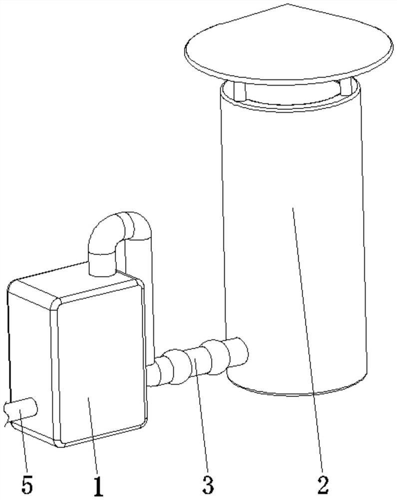
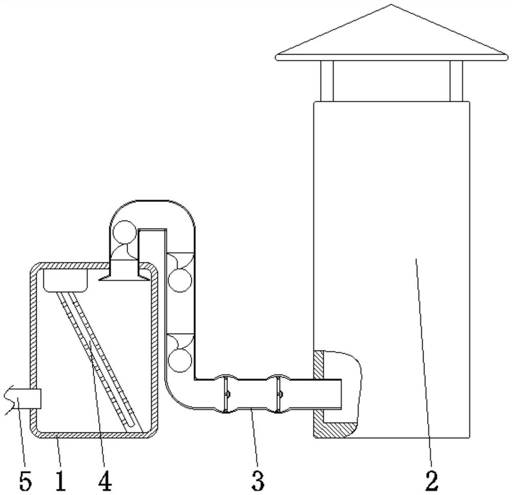
[0034] see Figure 1-8, the present invention provides a technical solution: a flue gas denitrification equipment, including a mixing chamber 1, a denitrification chamber 2, a delivery pipe device 3, an ammonia injector 4, and an air intake pipe 5, and the delivery pipe device 3 is fixedly connected between the mixing chamber 1 and the Between the denitrification chambers 2, the ammonia injector 4 is arranged inside the mixing chamber 1, and the air inlet pipe 5 is fixed on the bottom side of the surface of the mixing chamber 1 and communicates with the mixing chamber 1;

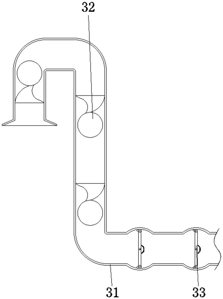
[0035] The conveying pipe device 3 is provided with a meandering pipe 31, a primary mixing device 32, and a secondary mixing device 33. One end of the meandering pipe 31 communicates with the top side of the mixing chamber 1, and the end of the meandering pipe 31 away from the mixing chamber 1 is connected to the denitrification chamber 2. The bottom side of the surface of the surface is connected, the prima...

Embodiment example 2

[0039] The secondary mixing device 33 is provided with a first flow guiding device 331, a second flow guiding device 332, an arc spring 333, and a limit block 334. Inside, one end of the first flow guiding device 331 is rotationally connected to one end of the second flow guiding device 332, and the arc spring 333 is fixed at a position corresponding to the surface of the first flow guiding device 331 and the surface of the second flow guiding device 332 The ends of the first flow guiding device 331 and the second flow guiding device 332 away from the arc spring 333 are connected to the inner wall of the meandering pipe 31 by rollers, and the limit block 334 is fixed on the inner wall of the meandering pipe 31 and close to the first flow guiding device 331, the position of the end of the second flow guide device 332, under the blowing of the gas, the first flow guide device 331 and the second flow guide device 332 are both turned into a V shape, and the mixed gas after the prim...


PUM


Abstract

The invention discloses flue gas denitration equipment, which comprises a mixing chamber, a denitration chamber, a conveying pipe device, an ammonia spraying device and a gas inlet pipe. The conveying pipe device is fixedly connected between the mixing chamber and the denitration chamber, the gas inlet pipe is fixed to one side of the bottom of the surface of the mixing chamber and communicates with the mixing chamber, one end of a zigzag pipeline is communicated with one side of the top of the mixing chamber, the end, away from the mixing chamber, of the zigzag pipeline is communicated with one side of the bottom of the surface of the denitration chamber, a first-stage mixing device is arranged in the zigzag pipeline and close to the mixing chamber, and a secondary mixing device is arranged in the zigzag pipeline and is close to the denitration chamber. The invention relates to the technical field of denitration equipment. According to the flue gas denitration equipment, the purpose of uniform mixing is achieved, flue gas and ammonia gas can make full contact, mixing is rapid and uniform, follow-up denitration work is facilitated, emission of harmful substances is reduced, pollution to the environment is reduced, human health is facilitated, and the use performance is improved.

Description

technical field [0001] The invention relates to the technical field of denitration equipment, in particular to a flue gas denitration equipment. Background technique [0002] Flue gas denitrification is mainly to remove the nitrogen oxides in the flue gas, so as to avoid the pollution of the atmosphere, soil and water due to the high concentration of nitrogen oxides discharged into the atmosphere. Whether burning garbage in daily life or in industrial manufacturing, it is inevitable that a large amount of smoke will be produced. Many substances in the smoke contain nitrate elements, which will pollute the environment when discharged into the air, and will cause harm to people's health after being inhaled by the human body. serious hazard. China is a country where coal is the main energy source. Coal accounts for 75% of primary energy, of which more than 84% is used through combustion. Nitrogen oxides (NOx) in the exhaust gas released by coal combustion are the main atmosphe...

Claims


Application Information

Patent Timeline
Patent Type & Authority Applications(China)
IPC IPC(8): B01F13/10B01D53/76B01D53/56
CPCB01D53/76B01D53/56B01D2258/0291B01F33/821
Inventor 不公告发明人
Owner 陈世君
Why Eureka
Try Eureka