Microreactor and manufacturing method thereof
A micro-reactor, micro-reaction chamber technology, applied in chemical instruments and methods, chemical/physics/physicochemical reactors, chemical/physics/physicochemical processes, etc.
- Summary
- Abstract
- Description
- Claims
- Application Information
AI Technical Summary
Problems solved by technology
Method used
Image
Examples
Embodiment 1
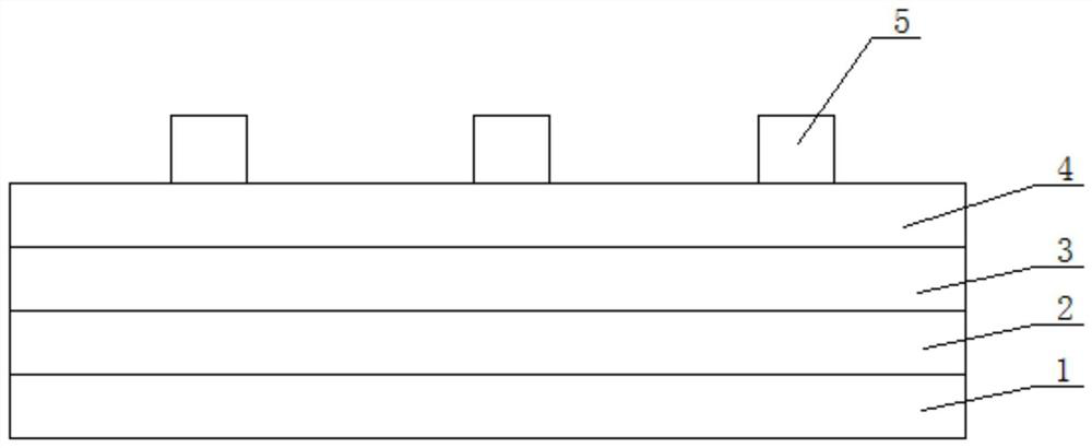
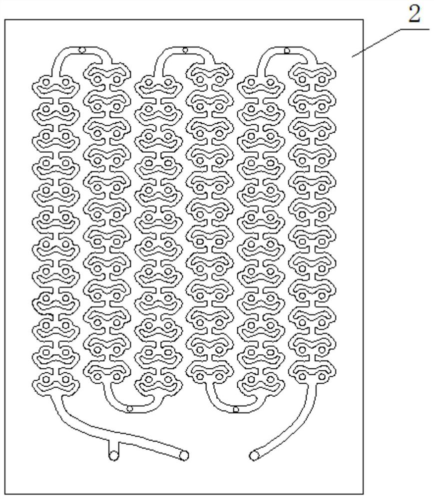
[0032] exist Figure 1~4 Among them, the microreactor in this embodiment is composed of the lower thermal bath substrate 1, the reaction channel substrate 2, the upper thermal bath substrate 3, the cover plate 4, and the filter device 5. The structure of the microreactor body is that the lower thermal bath substrate 1 The reaction channel substrate 2 is glued with glue, the reaction channel substrate 2 is glued with the upper heat bath substrate 3 with glue, the upper heat bath substrate 3 is glued with the cover plate 4 with glue, and the upper preheating substrate is the substrate The upper part is processed with S-shaped distribution of bath heat channels, the structure of the lower heat bath base plate 1 is the same as that of the upper heat bath base plate 3, and rectangular support plates are evenly distributed in the bath heat channel, and heating oil is passed into the bath heat channel. It is used to heat the reaction liquid. The reaction channel plate is processed wi...
Embodiment 2
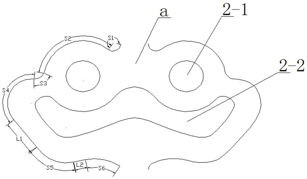
[0036] In this embodiment, the reaction channel plate is processed with 6 end-to-end connected micro-reaction channels on the substrate. One end of the micro-reaction channel is an inlet and the other end is an outlet. Each micro-reaction channel is connected end-to-end by 12 micro-reaction chambers a The micro-reaction chamber a of two adjacent micro-reaction channels is distributed in a staggered manner. The micro-reaction chamber a is in the shape of a frog face. The left and right contours of the micro-reaction chamber a are symmetrical about the center line. The left contour is composed of The arc S1 with the center outward, the arc S2 with the center inward, the arc S3 with the center outward, the arc S4 with the center inward, the straight line L1, the arc S5 with the center inward, the straight line L2, the outward arc The arc S6 is connected sequentially, the straight line L1 is connected tangentially with the arc S4 and the arc S5, the straight line L2 is connected ta...
Embodiment 3
[0039] In this embodiment, the reaction channel plate is processed with 6 end-to-end connected micro-reaction channels on the substrate. One end of the micro-reaction channel is an inlet and the other end is an outlet. Each micro-reaction channel is connected end-to-end by 12 micro-reaction chambers a The micro-reaction chamber a of two adjacent micro-reaction channels is distributed in a staggered manner. The micro-reaction chamber a is in the shape of a frog face. The left and right contours of the micro-reaction chamber a are symmetrical about the center line. The left contour is composed of The arc S1 with the center outward, the arc S2 with the center inward, the arc S3 with the center outward, the arc S4 with the center inward, the straight line L1, the arc S5 with the center inward, the straight line L2, the outward arc The arc S6 is connected sequentially, the straight line L1 is connected tangentially with the arc S4 and the arc S5, the straight line L2 is connected ta...
PUM
 Abstract
Description
Claims
Application Information
 - R&D
- Intellectual Property
- Life Sciences
- Materials
- Tech Scout
- Unparalleled Data Quality
- Higher Quality Content
- 60% Fewer Hallucinations
Browse by: Latest US Patents, China's latest patents, Technical Efficacy Thesaurus, Application Domain, Technology Topic, Popular Technical Reports.
© 2025 PatSnap. All rights reserved.Legal|Privacy policy|Modern Slavery Act Transparency Statement|Sitemap|About US| Contact US: help@patsnap.com


