Perforating device for constructional engineering

A punching device, construction engineering technology, applied in positioning devices, feeding devices, manufacturing tools and other directions, can solve the problems of high labor intensity, staff injury, danger, etc., to reduce the number of clamping times, high automation intensity, and improve work The effect of efficiency

Pending Publication Date: 2021-06-08
南力建设集团有限公司
View PDF0 Cites 2 Cited by
  • Summary
  • Abstract
  • Description
  • Claims
  • Application Information

AI Technical Summary

Problems solved by technology

[0003] The existing manual hand-held punching machine is used to punch the round pipes used in construction projects, which is not only labor-intensive, time-consuming and labor-intensive, but also extremely dangerous, which is easy to cause injury to the staff and is not c

Method used


Image

  • Perforating device for constructional engineering
  • Perforating device for constructional engineering
  • Perforating device for constructional engineering

Examples


Example Embodiment

[0026] Example

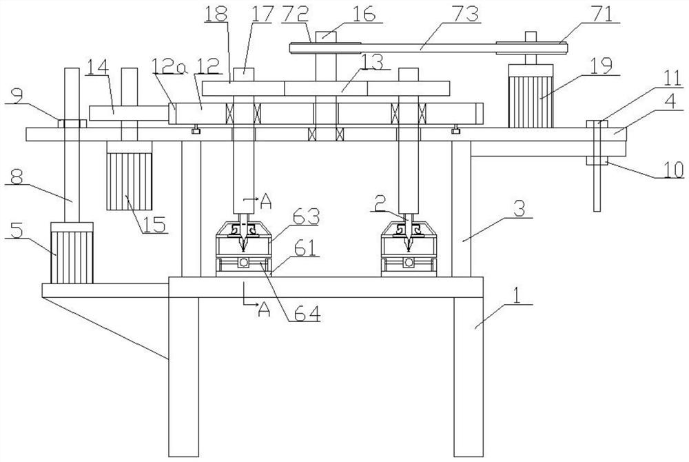
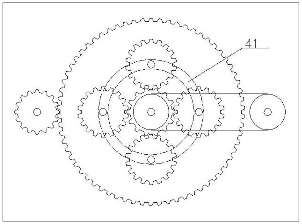
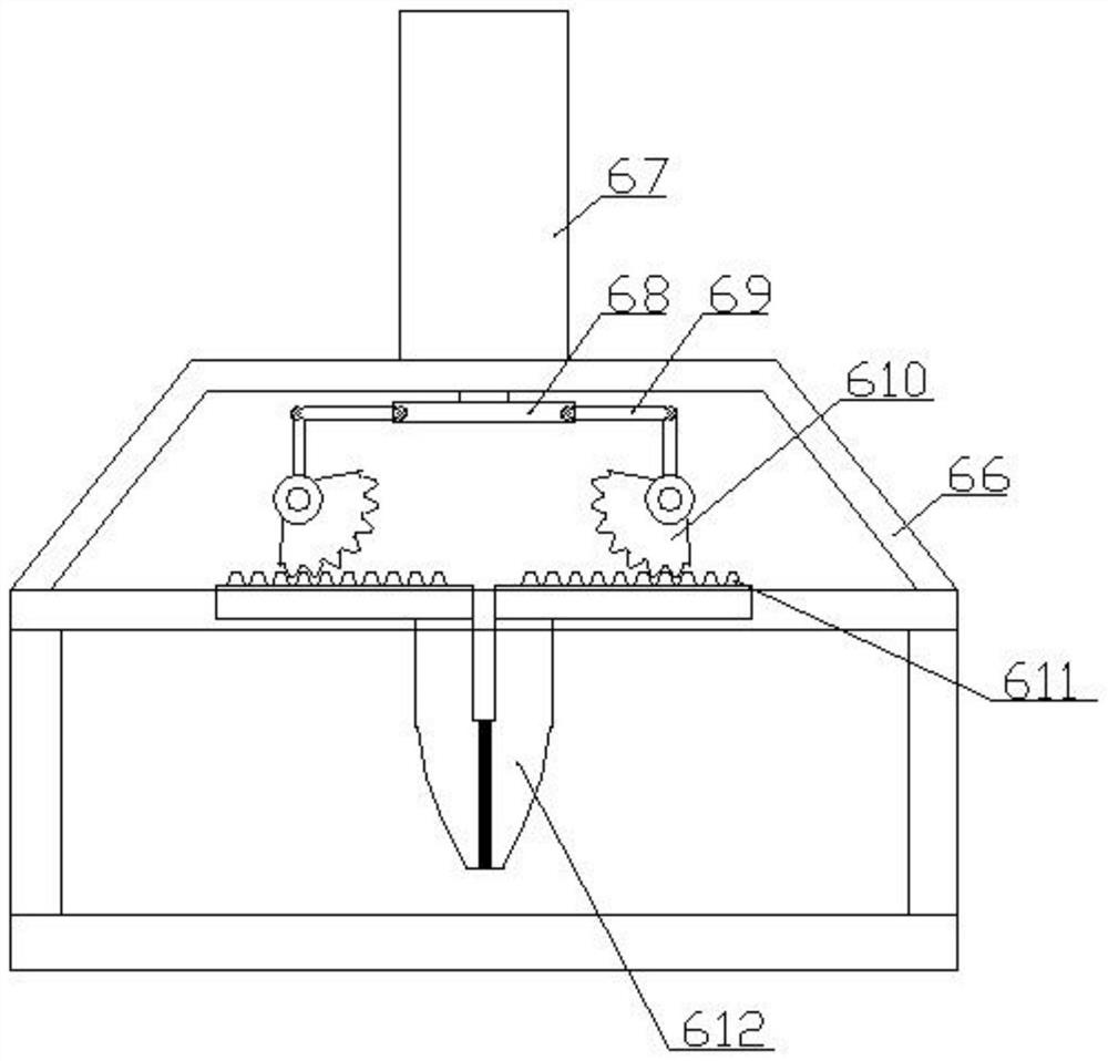
[0027] refer to figure 1 , figure 2 , image 3 , Figure 4 and Figure 5, a punching device for construction engineering, comprising a frame 1, a drill bit 2 arranged on the frame, a fixing plate 3 is fixedly connected to the left and right sides of the upper end face of the frame 1, and a fixing plate 3 is fixed between the two fixing plates 3 There is a lifting plate 4 above the frame 1, a first gear motor 5 is fixedly connected to the left side of the frame 1, and a wire rod 8 is fixedly connected to the tail of the output shaft of the first gear motor 5, and the tail of the screw rod 8 passes through the lifting plate. After 4, it is threadedly connected with the screw nut 9 on the lifting plate 4. The other end of the lifting plate 4 and the fixing plate 3 on the right side of the frame are slidably connected through the guide rod 11 and the guide sleeve 10. A disk 12 is slidably connected on the upper end surface, an annular rack plate 12a is arran...


PUM


Abstract

The invention discloses a perforating device for constructional engineering. The perforating device comprises a rack and drill bits, wherein fixed plates are arranged at the two sides of the rack correspondingly; a lifting plate is arranged above the position between the two fixed plates; the rack is provided with a first gear motor; the first gear motor is provided with a lead screw; the lead screw is in threaded connection with a feed screw nut; the lifting plate is slidably connected to the fixed plates through a guide rod and a guide sleeve; the lifting plate is slidably connected to a disc; the disc is provided with an annular rack plate; a first driving gear is rotationally arranged at the left side of the lifting plate; the first driving gear sleeves an output shaft of a second gear motor; the lifting plate is rotationally connected to a rotary shaft; the rotary shaft is connected to a second driving gear; the lifting plate is provided with a third gear motor; the third gear motor is connected to the rotary shaft through a transmission device; the disc is rotationally connected to a plurality of rotating shafts; the rotating shafts are provided with driven gears; the driven gears are in meshed connection with the second driving gear; the tails of the rotating shafts are fixedly connected to the drill bits; and the perforating device further comprises a clamping and moving device.

Description

technical field [0001] The invention relates to the field of construction equipment, in particular to a drilling device for construction engineering. Background technique [0002] Construction engineering refers to engineering entities formed through the construction of various housing buildings and their ancillary facilities and the installation of supporting lines, pipelines, and equipment. Internal space is a project that meets the needs of people's production, living, learning, and public activities. Architectural engineering is an important branch of civil engineering. In a broad sense, architectural engineering and civil engineering should belong to the same concept. Therefore, the basics of architectural engineering The attributes are generally consistent with the basic attributes of civil engineering. The construction of an engineering facility generally needs to go through three stages of survey, design and construction, and requires the use of engineering geologica...

Claims


Application Information

Patent Timeline
IPC IPC(8): B23B41/02B23B47/20B23Q3/08
CPCB23B41/02B23Q3/08B23Q5/28
Inventor 庄煌南庄念锐庄铭轩庄佳清庄煌培
Owner 南力建设集团有限公司
Why Eureka
Try Eureka