Ultrasonic resistance spot welding device and method for dissimilar metal

A technology of resistance spot welding and dissimilar metals, which is applied in the direction of resistance welding equipment, metal processing equipment, welding equipment, etc., and can solve problems such as failure, phase difference ultrasonic, etc.

Pending Publication Date: 2021-06-08
HUAZHONG UNIV OF SCI & TECH
View PDF0 Cites 0 Cited by
  • Summary
  • Abstract
  • Description
  • Claims
  • Application Information

AI Technical Summary

Problems solved by technology

[0005] In view of the above defects or improvement needs of the prior art, the present invention provides a device and method for ultrasonic resistance spot welding of dissimilar metals.

Method used


Image

  • Ultrasonic resistance spot welding device and method for dissimilar metal

Examples


Embodiment 1

[0044] Adopt device and method of the present invention to weld 75Lx25Wx1.3Tmm3Trip780 steel and 75Lx25Wx1.6Tmm3 606l aluminum alloy workpiece, concrete operation is as follows,

[0045] The workpiece steel and the workpiece aluminum are fixed with a fixture, and the workpiece aluminum is placed above the workpiece steel. The servo control device is used to drive the first electrode and the second electrode to apply a welding force of 3200N to the workpiece to be welded. Turn on the ultrasonic generating mechanism at the same time, so that the vibrating part vibrates on the steel surface of the workpiece, the amplitude is 30 μm, and the ultrasonic frequency is 20 kHz; a welding alternating current is passed between the first electrode and the second electrode, the current amplitude is 19 kA, and the heating time is 0.3 s; in the cooling and crystallization stage, the pressure maintenance time after resistance welding is 1s, and the ultrasonic maintenance time is 0.3s.

Embodiment 2

[0047] Using the device and method of the present invention to weld 75 L x25 W x1.5 T mm 3 Trip780 steel and 75 L x25 W x2 T mm 3 606l aluminum alloy workpiece, the specific operation is as follows:

[0048] Fix the workpiece steel and workpiece aluminum with a fixture, wherein the workpiece aluminum is placed above the workpiece steel, use a servo control device to drive the first electrode and the second electrode to apply a welding force of 3400N to the workpiece to be welded, the preload time is 1s, and the welding force is 0.7s Turn on the ultrasonic generating mechanism at the same time, so that the vibrating head vibrates on the steel surface of the workpiece, the amplitude is 35 μm, and the ultrasonic frequency is 20 kHz; the welding AC current is passed between the first electrode and the second electrode, the current amplitude is 22 kA, and the heating time is 0.4 s; in the cooling and crystallization stage, the pressure maintenance time after resistance weldi...


PUM


Abstract

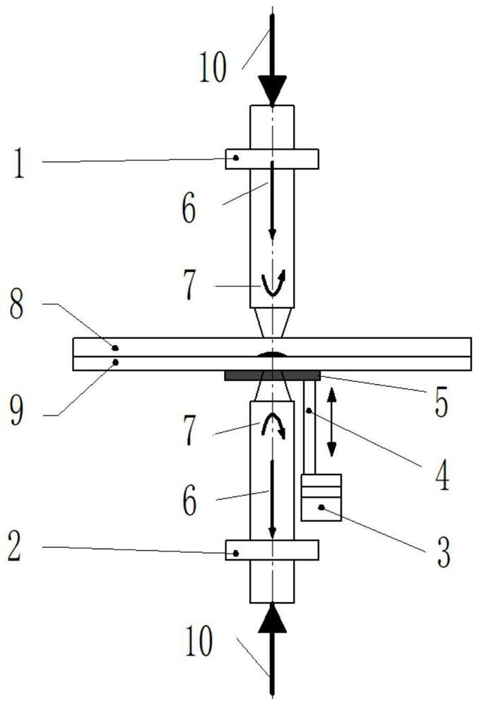
The invention discloses an ultrasonic resistance spot welding device and method for dissimilar metal, and belongs to the technical field of welding. The ultrasonic resistance spot welding device comprises a first electrode, a second electrode, an ultrasonic generation mechanism and a vibration piece; the first electrode and the second electrode are coaxially arranged on the two sides of the overlapped metal plate, and a welding head of the first electrode and a welding head of the second electrode are oppositely arranged; and the vibration piece is arranged outside the welding head of the second electrode in a sleeving mode, forms a vibration head with the welding head of the second electrode and makes contact with the metal plate, and the ultrasonic generation mechanism is connected to the vibration piece and used for providing ultrasonic waves for the vibration piece, so that the vibration piece can vibrate in the axial direction of the first electrode and the second electrode. The second electrode is arranged on the annular vibration piece in a sleeving mode, so that movement of the first electrode and fixation of the second electrode are facilitated, the indentation rate and warping of an upper workpiece can be effectively reduced, the welding work space is saved, and industrial production and manufacturing are facilitated; and in addition, ultrasonic failure caused by phase difference of amplitude shared by the first electrode, the second electrode and the vibration piece is avoided.

Description

technical field [0001] The invention belongs to the field of welding technology, and more specifically relates to an ultrasonic resistance spot welding device and method for dissimilar metals. Background technique [0002] The resistance spot welding of dissimilar metals connects two or more materials with different properties through the spot welding method, which meets the performance requirements while reducing production costs and maximizing resource utilization. Lightweight automobiles are an important way to solve the waste of resources in modern society. Light alloy materials such as aluminum alloys and magnesium alloys have become important body structural materials due to their low density, high strength, strong corrosion resistance, and good processing performance. However, due to the price and load-bearing strength requirements, dissimilar metal welding with steel is often considered in engineering, which can not only meet the performance requirements, but also re...

Claims


Application Information

Patent Timeline
IPC IPC(8): B23K11/11B23K11/36
CPCB23K11/115B23K11/36
Inventor 王元勋李玄王凯张开诚
Owner HUAZHONG UNIV OF SCI & TECH
Why Eureka
Try Eureka