
Ceramic part sand blasting method, ceramic part and manufacturing method of ceramic part

A technology of ceramic parts and sandblasting, which is applied in the field of ceramic parts and its production, and the field of ceramic parts sandblasting, which can solve the problems of loose particles falling, unable to meet the requirements of surface roughness, and unable to control surface roughness, etc.

Pending Publication Date: 2021-06-08
BEIJING NAURA MICROELECTRONICS EQUIP CO LTD
View PDF7 Cites 0 Cited by
  • Summary
  • Abstract
  • Description
  • Claims
  • Application Information

AI Technical Summary

Problems solved by technology

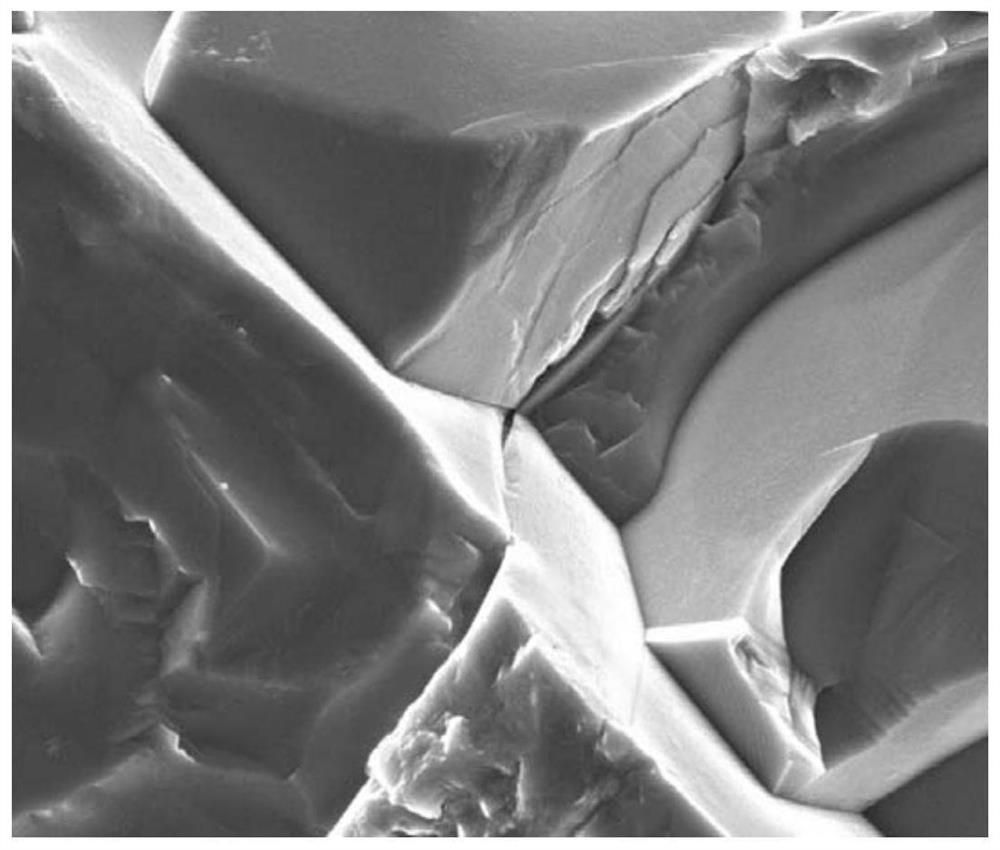
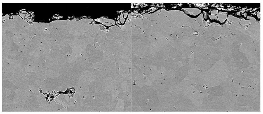
[0005] However, because the existing sandblasting process does not pay attention to the relevant parameters affecting the surface roughness, this will cause the problem of excessive sandblasting and the inability to control the surface roughness. the horizontal line (such as figure 1 shown), gaps (such as figure 2 Shown), etc., resulting in cracks and other damages, these damages are easy to produce loose particles falling on the surface of the wafer during the etching process, causing defects on the surface of the wafer, and will shorten the service life of ceramic parts and increase the replacement frequency, resulting in increased usage costs
The inability to control the surface roughness will limit the use of ceramic parts and cannot meet the requirements of different processes for the surface roughness of ceramic parts

Method used


Image

  • Ceramic part sand blasting method, ceramic part and manufacturing method of ceramic part
  • Ceramic part sand blasting method, ceramic part and manufacturing method of ceramic part
  • Ceramic part sand blasting method, ceramic part and manufacturing method of ceramic part

Examples


no. 1 example

[0035] see image 3 , the present embodiment provides a sandblasting method for ceramic parts, which includes performing the following steps cyclically:

[0036] S1. Spray sandblasting material on the surface of the ceramic part to be treated through the nozzle, and at the same time control the relative movement of the nozzle and the ceramic part until the sandblasting material covers the entire surface to be treated.

[0037] The above step S1 is used to obtain a certain surface roughness on the surface of the ceramic part. The so-called sand blasting refers to the use of compressed air as the power to form a high-speed jet beam to spray the sandblasting material onto the surface of the ceramic part to be treated at high speed. Due to the impact and cutting effect of the sandblasting material on the surface of the ceramic part, the surface of the ceramic part is obtained surface roughness.

[0038] Above-mentioned nozzle is for example the nozzle of sandblasting machine, be...

no. 2 example

[0055] Compared with the above-mentioned first embodiment, the sandblasting method for ceramic parts provided by this embodiment also includes step S1 which is executed cyclically, and controls the number of cycles of above-mentioned step S1 and the relevant parameters of each step S1. The parameters are the same as in the first embodiment described above.

[0056] In this embodiment, different sandblasting meshes are used in different times of step S1. That is to say, corresponding to each number of cycles, the number of sandblasting meshes used in each step S1 is independently set to different numbers, so as to ensure that the ceramic surface will not be damaged when each step S1 is performed.

[0057] Optionally, the number of blasting meshes decreases as the number of cycles increases. This not only helps to improve the uniformity of the surface roughness of the ceramic part, but also does not cause damage to the ceramic surface. Taking the number of sandblasting meshes ...


PUM


Abstract

The embodiment of the invention provides a ceramic part sand blasting method, a ceramic part and a manufacturing method of the ceramic part. The ceramic part sand blasting method comprises the following steps that S1, a sand blasting material is sprayed to the to-be-treated surface of the ceramic part through a nozzle, and meanwhile the nozzle and the ceramic part are controlled to move relatively till the whole to-be-treated surface is covered with the sand blasting material; the cycle index of S1 and related parameters of each S1 are set to be capable of controlling the surface roughness of the to-be-treated surface and reducing the surface damage of the ceramic part; the related parameters comprise at least one of the sand blasting material type, the injection pressure, the sand blasting mesh number, the sand blasting angle, the relative movement speed of the nozzle and the ceramic part, the nozzle diameter and the distance between a nozzle outlet and the to-be-treated surface. According to the ceramic part sand blasting method, the ceramic part and the manufacturing method of the ceramic part, damages such as cracks and the like can be reduced, and the surface roughness of the ceramic part is controlled, so that the requirements of different processes on the surface roughness of the ceramic part are met.

Description

technical field [0001] The invention relates to the field of semiconductor manufacturing, in particular to a sandblasting method for a ceramic part, a ceramic part and a manufacturing method thereof. Background technique [0002] In semiconductor processing equipment such as Inductive Coupled Plasma (ICP) etching equipment, the ceramic parts used are generally dielectric windows, nozzles, focus rings and the like. These ceramic parts are often distributed around the wafer. During the etching process, the surface of the ceramic parts will also be etched by plasma, resulting in changes in the surface structure of the ceramic parts and the formation of particles, which may fall on the wafer. On the round surface, the progress of etching is blocked, resulting in the formation of defects on the wafer surface, which directly affects the electrical index of the chip and the yield rate of the chip. [0003] In order to solve the above problems, the common practice is to roughen the...

Claims


Application Information

Patent Timeline
IPC IPC(8): B24C3/06B24C9/00B24C11/00
CPCB24C3/06B24C9/00B24C11/00
Inventor 范颖旭符雅丽郑友山王宏伟
Owner BEIJING NAURA MICROELECTRONICS EQUIP CO LTD
Learn More