Ozone generation control device and system

A technology for ozone generation and control devices, applied in the direction of oxidized water/sewage treatment, chemical instruments and methods, water/sludge/sewage treatment, etc. Small microbubbles and other problems, to achieve the best sewage treatment effect, reduce the generation of bromate, the overall effect of small size

Pending Publication Date: 2021-06-08
河南省奥瑞环保科技股份有限公司
View PDF7 Cites 0 Cited by
  • Summary
  • Abstract
  • Description
  • Claims
  • Application Information

AI Technical Summary

Problems solved by technology

However, the ozone contact reaction tank currently in use has the following shortcomings. The ozone microbubbles or ultramicrobubbles released by the aeration device are small in size and slow in rising speed, causing the ozone bubbles to accumulate on the surface of the aeration device for a long time. localized area, so the closer the location of the aeration device, the higher the concentration of ozone
Since sewage or tap water generally contains bromide ions, the long residence time of the fluid in the local area near the surface of the aeration device will caus

Method used


Image

  • Ozone generation control device and system
  • Ozone generation control device and system
  • Ozone generation control device and system

Examples


Example Embodiment

[0029] Example 1

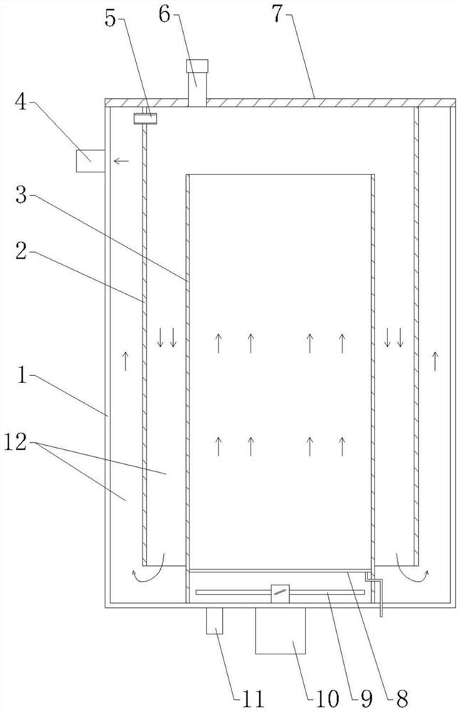
[0030] see figure 1As shown, the present invention provides an ozone generation control device, comprising a main tank 1, the top of the main tank 1 is provided with a detachable cover plate 7, the cover plate 7 is provided with an emptying port 6, the main tank 1 is provided with an inner cylinder 3, the lower end of the inner cylinder 3 is fixed with the bottom surface of the main pipe, the upper end of the inner cylinder 3 is lower than the height of the main tank 1 and the upper end is open, and the bottom of the main tank 1 is provided with a communication with the inner cylinder 3. There is a first spacer 2 between the main tank 1 and the inner cylinder 3, the upper end of the first spacer 2 is fixed with the bottom surface of the cover plate 7, and the lower end of the first spacer 2 is connected to the main tank. There is a gap between the bottom surfaces of the 1, the upper end side of the first spacer 2 is provided with a pressure equalizing port ...

Example Embodiment

[0032] Example 2

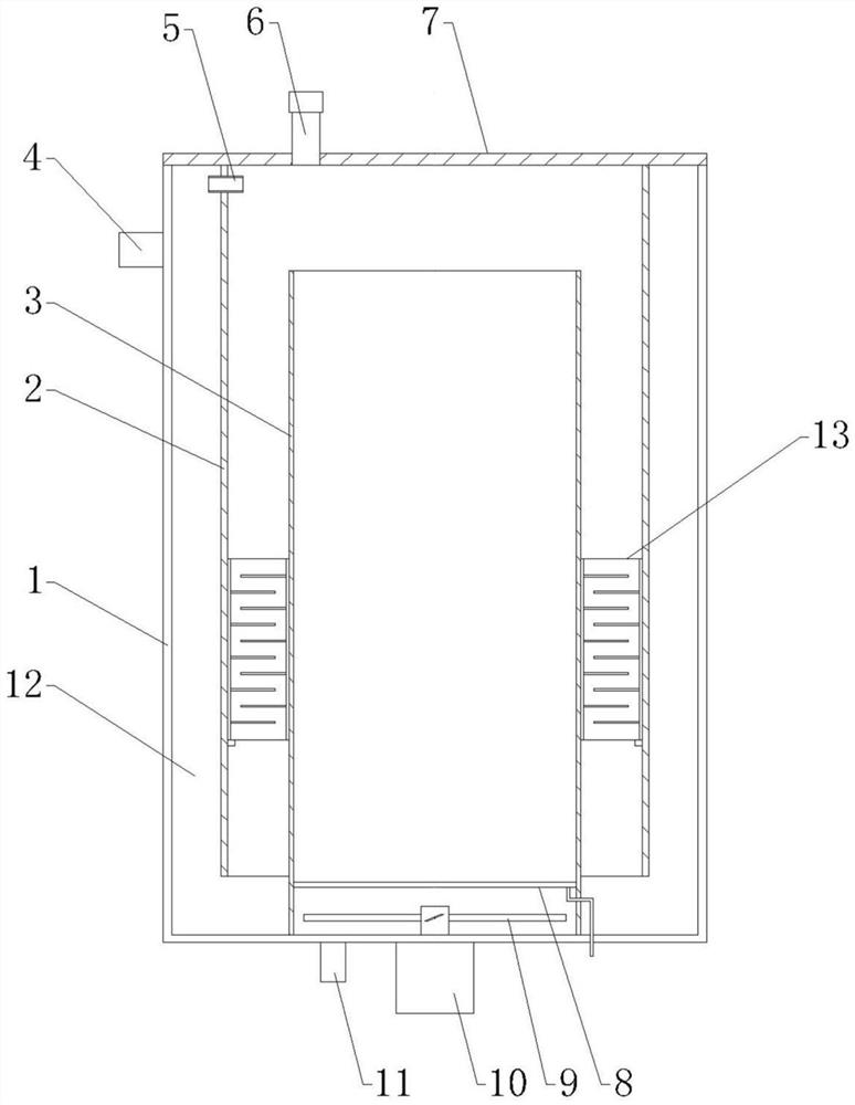
[0033] see figure 2 As shown, this embodiment is further improved on the basis of Embodiment 1. In this embodiment, a detachable first spacer is added in the slow flow channel 12 between the first spacer 2 and the inner cylinder 3 The flow damper 13, by adding the first damper 13, can further lengthen the purification process and purification time of the sewage, and further improve the sewage purification effect, and the first damper 13 is also easy to install and disassemble, which is convenient for later maintenance. .

[0034] Three preferred structures and installation methods of the first damper 13 are provided below:

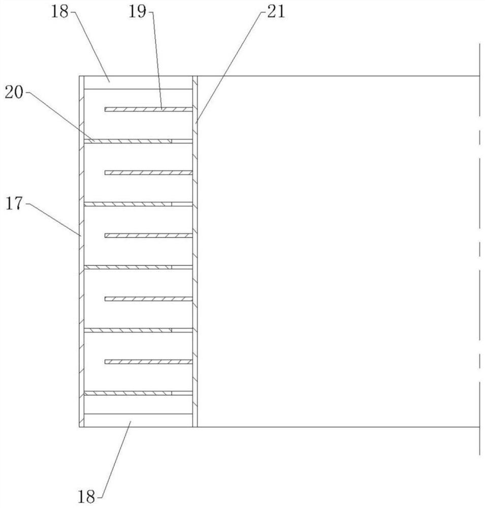
[0035] 1) see image 3 and Figure 4 As shown, the first damper 13 includes a first sleeve 17 and a second sleeve 21 disposed inside the first sleeve 17 , between the upper end of the first sleeve 17 and the upper end of the second sleeve 21 And the lower end of the first sleeve 17 and the lower end of the second sleeve 21 are conn...

Example Embodiment

[0038] Example 3

[0039] see Figure 10 As shown, this embodiment is further improved on the basis of implementation 2. In this embodiment, a second damper 14 is added in the slow flow channel 12 between the first spacer 2 and the main tank 1. The structure of the second damper 14 can be the same as any one of the three first dampers 13 provided in the second embodiment. The flow damper 14 can be matched with the installation space between the first spacer 2 and the main tank 1 .

[0040] see Figure 11 As shown, the present invention also provides an ozone generation control system, including an ozone generator 15, an air pump 16 connected to the ozone generator 15 and the aforementioned ozone generation control device, the aeration coil 8 is connected to the air pump through a pipeline The gas outlet end of 16 is connected, and ozone gas is supplied into the inner cylinder 3 by the ozone generator 15 . The ozone generation control system can effectively reduce the gener...


PUM


Abstract

The invention discloses an ozone generation control device and system, the ozone generation control device comprises a main tank, the top of the main tank is provided with a cover plate, the main tank is internally provided with an inner cylinder, and the bottom of the main tank is provided with a liquid inlet communicated with the inner cylinder; a first spacer bush is arranged between the main tank and the inner cylinder, a pressure equalizing opening is formed in the side face of the upper end of the first spacer bush, and slow flow channels used for liquid circulation are formed between the first spacer bush and the inner cylinder and between the first spacer bush and the main tank. A liquid outlet is formed in the side surface of the upper end of the main tank; a stirring device is arranged at the bottom of the main tank, a motor is arranged below the main tank, and an aeration coil pipe is arranged above the stirring device; the ozone generation control system comprises an ozone generator, an air pump and the ozone generation control device, and the aeration coil pipe is connected with the air outlet end of the air pump through a pipeline. The device can effectively reduce generation of bromate when ozone is used for water treatment, has a better sewage treatment effect, and is novel in structure and easy to manufacture, disassemble and assemble.

Description

technical field [0001] The invention relates to the technical field of fluid treatment by an ozone oxidation method, in particular to an ozone generation control device and system. Background technique [0002] In recent years, the ozone oxidation method has been widely used in food, pharmaceutical, water supply and other industries due to its advantages in sterilization, disinfection, decolorization, deodorization, oxidation of refractory organic matter and improvement of flocculation effect. Compared with conventional water treatment methods, ozone oxygen flotation oxidation method has better treatment effect on refractory substances, fast degradation speed, small footprint, high degree of automation, no secondary pollution, less scum and sludge generation, At the same time, it has the functions of sterilization, decolorization and anti-scaling. However, the ozone contact reaction tank currently in use has the following shortcomings. The ozone microbubbles or ultramicrobu...

Claims


Application Information

Patent Timeline
IPC IPC(8): C02F1/78
CPCC02F1/78C02F2201/784
Inventor 申剑陈星陈俊莹姜英杰
Owner 河南省奥瑞环保科技股份有限公司
Why Eureka
Try Eureka