Diabetic foot wound exudate detection chip

A technology of diabetic foot and exudate, applied in the direction of measuring devices, disease diagnosis, instruments, etc.

Active Publication Date: 2021-06-08
SHANGHAI UNIV
View PDF6 Cites 0 Cited by
  • Summary
  • Abstract
  • Description
  • Claims
  • Application Information

AI Technical Summary

Problems solved by technology

At present, there is a lack of effective means to quickly detect the recovery of the diseased foot of diabetic foot patients in the existing technology. Therefore, it is urgent to find a detection product that can quickly detect the recovery of the diseased foot of diabetic foot patients.

Method used


Image

  • Diabetic foot wound exudate detection chip
  • Diabetic foot wound exudate detection chip

Examples


Embodiment 1

[0038] Embodiment 1: Diabetic foot wound exudate detection pad

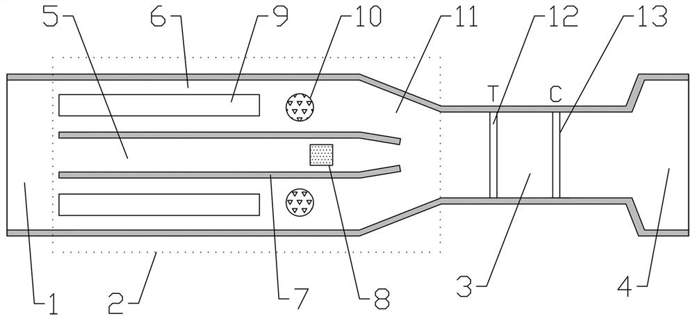
[0039] A detection pad for the detection of diabetic foot wound exudate, such as figure 1 As shown, the material of the detection pad is nitrocellulose membrane, and the detection pad is provided with a sample loading area 1, a channel area 2, a reaction area 3 and a water absorption area 4 which are sequentially connected along the length direction of the detection pad.

[0040] The channel area 2 includes a non-accelerating channel 5, the inlet end of the non-accelerating channel 5 communicates with the sample loading area 1, the outlet end of the non-accelerating channel 5 communicates with the reaction zone 3, and the outlet end of the non-accelerating channel 5 is a shrinkage port structure, The outlet end of the non-acceleration channel 5 is provided with a color developer coating area 8, and the color developer coating area 8 is coated with the color developer BCIP / NBT; both sides of the non-acceleration c...

Embodiment 2

[0048] Embodiment 2: Diabetic foot wound exudate detection chip

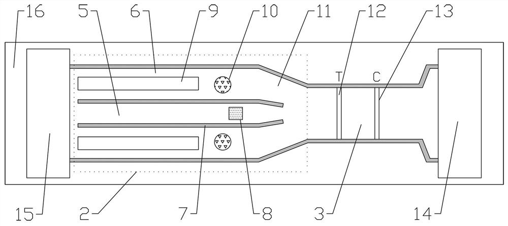
[0049] A kind of diabetic foot wound exudate detection chip, such as figure 2 As shown, it includes a base 16, the base 16 is a PVC board, the base 16 is pasted with the detection pad for detecting the exudate of the diabetic foot wound prepared in Example 1, and the sample pad 15 is provided on the sample loading area 1 of the detection pad. One end of the sample pad 15 is lapped on the sample loading area 1 of the detection pad, and the other end of the sample pad 15 is pasted on the base 16; an absorbent pad 14 is arranged on the water absorption area 4 of the detection pad, and one end of the absorbent pad 14 is lapped on the On the water-absorbing area 4 of the detection pad, the other end of the absorbent pad 14 is pasted on the base 16 . The material of the sample pad 15 is glass cellulose membrane, and the material of the absorbent pad 14 is absorbent filter paper.

[0050] The concrete method that ad...


PUM


Abstract

The invention belongs to the technical field of micro-fluidic chips, and discloses a diabetic foot wound exudate detection chip. The detection chip comprises a substrate, a detection pad is arranged on the substrate, and a sample adding area, a channel area, a reaction area and a water absorption area are arranged on the detection pad; the channel area comprises a non-acceleration channel, the inlet end of the non-acceleration channel is communicated with the sample adding area, the outlet end of the non-acceleration channel is communicated with the reaction area, a color developing agent coating area is arranged on the non-acceleration channel, and acceleration channels are arranged on the two sides of the non-acceleration channel; a drainage interval is arranged between the non-acceleration channel and the acceleration channels; the inlet ends of the acceleration channels are communicated with the sample adding area, an inclined channel is arranged at the outlet end of each acceleration channel, the acceleration channels are communicated with the reaction area through the inclined channels, and an antibody coating area is arranged on each acceleration channel; a detection line and a quality control line are arranged in the reaction area, and the outlet end of the reaction area is communicated with the water absorption area. The detection chip can rapidly detect whether wound exudate of a diabetic foot patient contains MMP-9 or not, the recovery condition of the wound of the patient can be known in time, and help is provided for follow-up treatment.

Description

technical field [0001] The invention relates to the technical field of microfluidic chip detection, in particular to a diabetic foot wound exudate detection chip. Background technique [0002] Microfluidic chips have attracted much attention because they can integrate detection items in traditional laboratories on a tiny chip, and have been widely used in biomedicine, environmental and food testing and other fields. [0003] On-site rapid detection (Point of Care Test, POCT) is an important field of in vitro diagnosis; it makes patients no longer need to go to the hospital to undergo complicated and time-consuming biochemical examinations, and only needs a miniaturized device to obtain the desired results . At present, the blood glucose meter is the most successful POCT device; patients can check their blood sugar status anytime and anywhere, and no longer need to go to the hospital for testing. [0004] As a branch of microfluidic chip, microfluidic paper analysis equipme...

Claims


Application Information

Patent Timeline
IPC IPC(8): G01N33/558G01N33/573
CPCG01N33/558G01N33/573G01N2333/96494G01N2800/042
Inventor 岳涛顾申瑜刘媛媛刘娜兰伟霞高守玮蔚延聪李恒宇谢少荣罗均
Owner SHANGHAI UNIV
Why Eureka
Try Eureka