CAN (Controller Area Network) communication circuit in equipment

A CAN communication and circuit technology, applied in the field of CAN communication, can solve the problems of increased equipment cost, large PCB layout space, increased equipment power consumption, etc., to reduce equipment power consumption, reduce equipment cost, and save PCB layout space Effect

Pending Publication Date: 2021-06-08
XIAMEN YAXON NETWORKS CO LTD
View PDF0 Cites 4 Cited by
  • Summary
  • Abstract
  • Description
  • Claims
  • Application Information

AI Technical Summary

Problems solved by technology

However, using a dedicated CAN transceiver chip in the same device for CAN communication will increase the cost of the de

Method used


Image

  • CAN (Controller Area Network) communication circuit in equipment
  • CAN (Controller Area Network) communication circuit in equipment

Examples


Example Embodiment

[0011] The invention is further illustrated in conjunction with the accompanying drawings and specific embodiments.
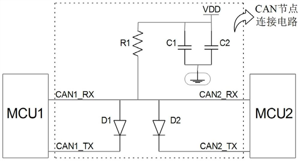
[0012] Such as figure 2 As shown, the CAN communication circuit inside the device, including the MCU 1, the MCU 2, and the CAN node connection circuit, and the MCU1 and the MCU 2 are connected via the CAN node connection circuit. MCU1, MCU2 is a processor having a CAN transceiver function. The CAN node connection circuit includes a pull-up resistor R1, a first diode D1, a second diode D2, and a pull-up resistor R1 connected to VDD, and the pull-up resistor R1 and the CAN2_Rx of the MCU1 CAN1_RX, MCU2, The first diode D1 anode, the second diode D2 anode is connected; the first diode D1 cathode is connected to the CAN1_TX of the MCU1; the second diode D2 cathode is connected to the CAN2_TX of the MCU2.

[0013] In order to cause the circuit to be uninterrupted, the CAN node connection circuit also includes a first capacitor C1 and a second capacitor C2, and the first...


PUM


Abstract

The invention relates to a CAN communication circuit in equipment, which comprises an MCU1, an MCU2 and a CAN node connecting circuit, the MCU1 and the MCU2 are connected through the CAN node connecting circuit, the MCU1 and the MCU2 are processors with CAN transceiving functions, the CAN node connecting circuit comprises a pull-up resistor R1, a first diode D1 and a second diode D2, one end of the pull-up resistor R1 is connected with a VDD, the other end of the pull-up resistor R1 is connected with a power supply, and the other end of the pull-up resistor R1 is connected with a power supply. The other end of the pull-up resistor R1 is connected with the CAN1RX of the MCU1, the CAN2RX of the MCU2, the anode of the first diode D1 and the anode of the second diode D2; the cathode of the first diode D1 is connected with the CAN1TX of the MCU1; and the cathode of the second diode D2 is connected with the CAN2TX of the MCU2. According to the CAN communication circuit, a special CAN transceiver chip is removed while the CAN bus communication function is guaranteed, the BOM cost of equipment is reduced, the power consumption of the equipment is reduced, and the PCB arrangement space is saved.

Description

technical field [0001] The invention relates to the field of CAN communication, in particular to a CAN communication circuit inside equipment. Background technique [0002] Nowadays, the high performance and high reliability of the CAN bus have been widely recognized, and are widely used in industrial automation, ships, medical equipment, industrial equipment, automotive electronics, etc. Usually in order to improve the CAN bus transmission distance, the CAN bus anti-interference ability, and ensure that multiple CAN nodes can complete high-quality communication, it is necessary to add a dedicated CAN transceiver chip (such as figure 1 ). However, using a dedicated CAN transceiver chip in the same device for CAN communication will increase the cost of the device on the one hand, increase the power consumption of the device on the other hand, and require a large PCB layout space. Contents of the invention [0003] The present invention aims to provide a CAN communication ...

Claims


Application Information

Patent Timeline
IPC IPC(8): H04L12/40
CPCH04L12/40006H04L2012/40215
Inventor 陈文顺何凌强李家祥
Owner XIAMEN YAXON NETWORKS CO LTD
Why Eureka
Try Eureka