Folded plate type demister for treating flue gas desulfurization waste gas

A technology for mist eliminators and waste gas, which is applied in gas treatment, chemical instruments and methods, membrane technology, etc., can solve the problems of huge water resource consumption and limited mist cleaning effect, so as to improve cleaning efficiency, save water consumption, High cleanliness effect

Active Publication Date: 2021-06-11
SHANDONG HAIHUI ENVIRONMENTAL PROTECTION EQUIP
View PDF5 Cites 0 Cited by
  • Summary
  • Abstract
  • Description
  • Claims
  • Application Information

AI Technical Summary

Problems solved by technology

However, due to the bent structure of the folded plate, a large amount of trapped mist often gathers at the corner of the folded plate. When the demister is cleaned, the amount of water directly flushed by the high-pressure water flow to the corner is less, and the cleaning of a large amount of mist Limited effect and therefore tend to consume huge water resources

Method used


Image

  • Folded plate type demister for treating flue gas desulfurization waste gas
  • Folded plate type demister for treating flue gas desulfurization waste gas
  • Folded plate type demister for treating flue gas desulfurization waste gas

Examples


Embodiment 1

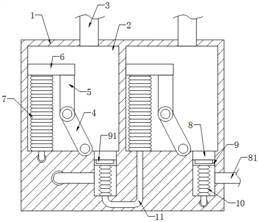
[0023] refer to figure 1 , a folding-plate demister for treating flue gas desulfurization waste gas, comprising a protective shell 1, two defogging chambers 2 are provided on the side wall of the protective shell 1, and an air intake pipe 3 is provided on the inner top of the demistering chamber 2, The inner bottom of the demister chamber 2 is rotatably connected with a first separation plate 4, the upper end of the first separation plate 4 is rotatably connected with a second separation plate 5, and the upper end of the second separation plate 5 is fixedly connected with a support plate 6. It should be noted that , the support plate 6 is slidably connected to the inner wall of the demisting chamber 2, and a chute 8 is provided at the bottom of the demisting chamber 2, and a driving device for driving the support plate 6 to move up and down is installed in the chute 8, and the sealing sliding connection in the chute 8 There is a slide plug 9, the upper end of the slide plug 9 ...

Embodiment 2

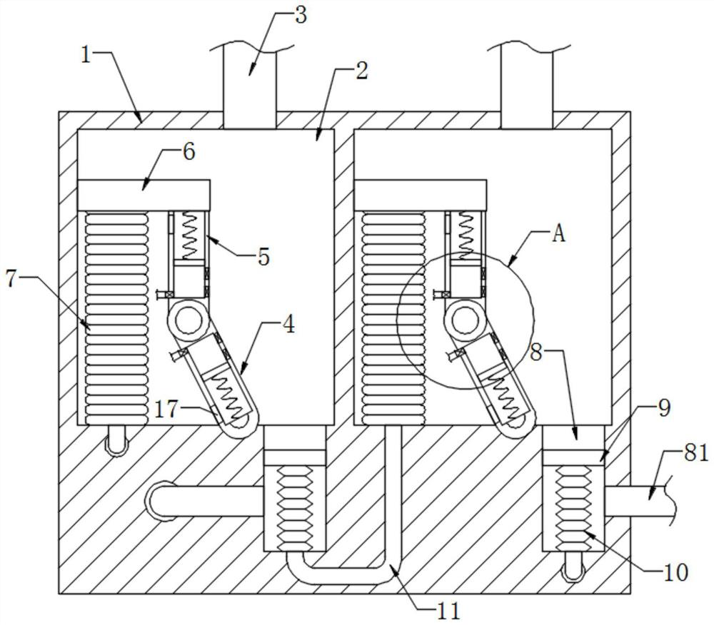
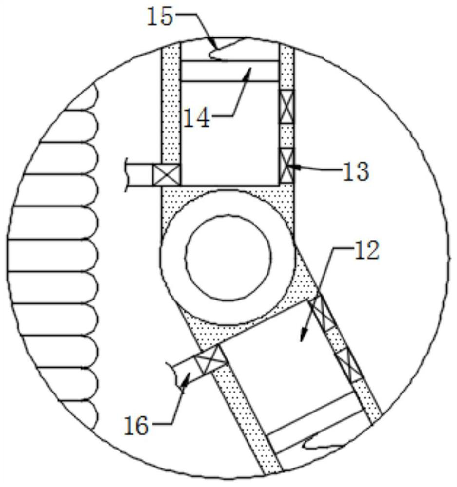
[0030] refer to Figure 2-3 , different from Embodiment 1, the sidewalls of the first separation plate 4 and the second separation plate 5 all start to have an air suction groove 12, and a magnetic piston 14 is sealed and slidably connected in the air suction groove 12, and the two magnetic pistons The opposite magnetic poles of the piston 14 are opposite, and the magnetic piston 14 is elastically connected to the inner wall of the air suction groove 12 through the spring 15, and a plurality of one-way air inlet holes 13 are provided on the inner wall of the air suction groove 12.

[0031] A one-way air outlet pipe 16 is provided on the inner wall of the suction groove 12, and a plurality of one-way air inlet holes 13 are all close to the rotational connection of the first separation plate 4 and the second separation plate 5, and the air outlet end of the one-way air outlet pipe 16 is arranged on In addition to the mist chamber 2, the one-way air inlet 13 only allows air to fl...


PUM


Abstract

The invention discloses a folded plate type demister for treating flue gas desulfurization waste gas. The folded plate type demister comprises a protective shell, two demisting cavities are formed in the side wall of the protective shell, air inlet pipes are arranged at the inner tops of the demisting cavities, and first separation plates are rotationally connected to the inner bottoms of the demisting cavities; a second separation plate is rotatably connected to the upper end of the first separation plate, a supporting plate is fixedly connected to the upper end of the second separation plate, a sliding groove is formed in the bottom in the demisting cavity, and a driving device for driving the supporting plate to move up and down is installed in the sliding groove. By alternately blowing entrainment-containing airflow into the two demisting cavities, the two supporting plates can be sequentially driven to move up and down under the action of the driving device, so that the included angle between the first separation plate and the second separation plate is continuously changed, the entrainment gathered at the corner is guided into the interception tank, the washing difficulty can be greatly reduced, and meanwhile, the consumption of water resources for cleaning can be saved.

Description

technical field [0001] The invention relates to the related technical field of flue gas desulfurization equipment, in particular to a folding-plate mist eliminator for treating waste gas from flue gas desulfurization. Background technique [0002] In the waste gas treatment process of wet desulfurization, the pollutants in the flue gas are often sprayed into slurry through the spray tower, and the mist eliminator captures the mist particles and slurry droplets entrained in the flue gas. [0003] Among them, the folded plate demister is through the gas containing mist flowing into the demister, and the mist collides with the corrugated folded plate, its kinetic energy is reduced, the speed is reduced, and it is trapped on the surface of the folded plate. However, due to the bent structure of the folded plate, a large amount of trapped mist often gathers at the corner of the folded plate. When the demister is cleaned, the amount of water directly flushed by the high-pressure w...

Claims


Application Information

Patent Timeline
Patent Type & Authority Applications(China)
IPC IPC(8): B01D45/08B01D53/80B01D53/48
CPCB01D45/08B01D53/80B01D53/48B01D2258/0283
Inventor 侯泽鹏
Owner SHANDONG HAIHUI ENVIRONMENTAL PROTECTION EQUIP
Why Eureka
Try Eureka