Turbine blade branch net type cooling structure

A technology for cooling structure and turbine blades, which is applied in the direction of supporting components of blades, engine components, machines/engines, etc. It can solve the problems of small heat exchange area and cooling efficiency that cannot meet high thrust-to-weight ratio aeroengines, etc., to achieve increased cooling area, The effect of improving the heat exchange capacity

Active Publication Date: 2021-06-11
DALIAN UNIV OF TECH
View PDF14 Cites 0 Cited by
  • Summary
  • Abstract
  • Description
  • Claims
  • Application Information

AI Technical Summary

Problems solved by technology

Due to the small heat exchange area of ​​this type of structure and less disturbance to the airflow, its cooling efficiency cannot meet the needs of high thrust-to-weight ratio aeroengines, and it is urgent to improve it.

Method used


Image

  • Turbine blade branch net type cooling structure
  • Turbine blade branch net type cooling structure
  • Turbine blade branch net type cooling structure

Examples


Embodiment 1

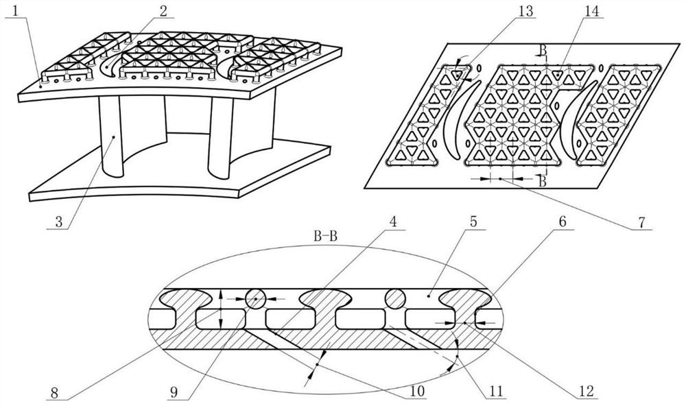
[0031] figure 2 It is a schematic diagram of a turbine guide vane with a branched cooling structure provided by an embodiment of the present invention. As shown in the figure, the branch network cooling structure of this embodiment is composed of two parts: a cylindrical support structure and a network connection structure. The cylindrical support structure in the branch-network cooling structure is perpendicular to the outer surface of the turbine guide blade edge plate, and the mesh connection structure is approximately parallel to the outer surface of the edge plate.

[0032] The cylindrical support structure in the branch network cooling structure is defined by the diameter φD 1 The cylinders of =1 mm are arranged in an equilateral triangle, each cylinder is located at the vertices of the equilateral triangle, and the side length of the equilateral triangle is the distance L=3mm between two adjacent cylinders.

[0033] The network connection structure in the branch netw...

Embodiment 2

[0036] A turbine guide vane with a branch-network cooling structure, the cylindrical support structure in the branch-network cooling structure is defined by the diameter φD 1 = 2mm columns, arranged in a regular triangle, each column is located at the apex of the regular triangle, the side length of the regular triangle is the distance between two adjacent columns L = 5mm, the typical value can be 4mm.

[0037] The network connection structure in the branch network cooling structure is determined by the diameter φD 2 = 2mm column, the total height of the branch network cooling structure H = 3mm, the diameter of the air film hole φd = 0.8mm, the angle ∠A between the axis of the air film hole and the outer surface of the edge plate 2 = 40°. The ratio of the diameter of the gas film pores to the network connection is in the range of 0.8.

Embodiment 3

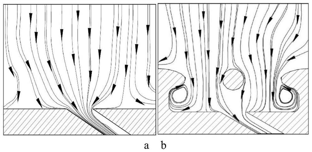
[0039] In the layout of the air film hole, a mode with less flow resistance can be adopted, that is, the cooling air inlet is arranged directly under the triangular mesh, as shown in Image 6 shown. Compared with the first embodiment, although this form reduces the cooling air flow distance and the cooling effect is reduced, it also reduces the flow resistance and loss, and also has the advantage of being easy to observe the clogging of the orifice. Therefore, the position of the air film hole can be reasonably arranged according to different working conditions and the cooling requirements of different positions of the edge plate under the condition that the size of the branch network structure remains unchanged, so as to maximize the utilization of cooling air.


PUM


Abstract

The invention belongs to the technical field of aero-engine turbine blade cooling, and particularly relates to a turbine blade branch net type cooling structure. A cylinder supporting structure in the branch net type cooling structure is perpendicular to the outer surface of a turbine guide blade margin plate, and a net-shaped connecting structure is approximately parallel to the outer surface of the margin plate. The cylinder supporting structure in the branch net type cooling structure is composed of cylinders with the diameter phi D1, the cylinders are arranged in a regular triangle shape, the cylinders are located at the vertexes of the regular triangle respectively, and the side length of the regular triangle, namely the distance L between every two adjacent cylinders, is 3-5 mm. Compared with a conventional cooling scheme, the structure covers the outer surface of the margin plate, the heat exchange area on the cold air side can be remarkably increased, the disturbance degree of cooling airflow is enhanced, and therefore the cooling effect is effectively improved. In addition, the anti-deformation capacity of the margin plate can be enhanced through the structure, and manufacturing is easy.

Description

technical field [0001] The invention belongs to the technical field of aero-engine turbine blade cooling, and relates to a turbine blade branch-net type cooling structure. Background technique [0002] An aero engine is a power device that converts thermal energy into jet thrust or mechanical work. The higher the temperature in front of the turbine, the greater the thrust and the higher the engine performance. Data predictions show that for every 100°C increase in the gas temperature in front of the turbine, the thermal efficiency of the engine will increase by 8%, and the maximum thrust will increase by about 15%. Therefore, increasing the gas temperature has become the primary pursuit of the design. Under such conditions, the temperature resistance of the turbine blade, which is a typical hot-end component, becomes the bottleneck factor restricting the performance improvement of the aero-engine. In the case that it is difficult to further improve the high temperature res...

Claims


Application Information

Patent Timeline
Patent Type & Authority Applications(China)
IPC IPC(8): F01D5/18
CPCF01D5/186F01D5/187
Inventor 吕东康浩梁彩云苏航王楠孙一楠
Owner DALIAN UNIV OF TECH
Why Eureka
Try Eureka