Manifold type micro-channel heat sink with boss-like structure

A boss structure and micro-channel technology, which is applied to laser components, laser cooling devices, laser components, etc., can solve problems such as increased heat sink costs, uneven temperature, and large flow resistance of micro-channel structures, so as to increase the temperature Uniformity, uniform temperature, solve the effect of large flow resistance

Pending Publication Date: 2021-06-11
CHINA ELECTRONICS TECH GROUP CORP NO 16 INST
View PDF0 Cites 0 Cited by
  • Summary
  • Abstract
  • Description
  • Claims
  • Application Information

AI Technical Summary

Problems solved by technology

[0005] Existing heat dissipation methods for laser crystals mostly use microchannels and diamond heat expansion plates to solve the problems of high heat flow heat dissipation and temperature uniformity of laser crystals. On the one hand, the traditional microchannel structure has a large flow resistance, and the manifold microchannel structure is adopted. Although the heat sink can effectively reduce the flow resistance, it will still cause large temperature inhomogeneity at the entrance of the microchannel due to the impact of the inflow; on the other hand, the use of diamond as the heat expansion material will greatly increase the cost of the heat sink

Method used


Image

  • Manifold type micro-channel heat sink with boss-like structure
  • Manifold type micro-channel heat sink with boss-like structure
  • Manifold type micro-channel heat sink with boss-like structure

Examples


Embodiment Construction

[0022] In order to make the purpose, technical solutions and advantages of the embodiments of the present invention clearer, the technical solutions in the embodiments of the present invention will be clearly and completely described below in conjunction with the drawings in the embodiments of the present invention. Obviously, the described embodiments It is a part of embodiments of the present invention, but not all embodiments.

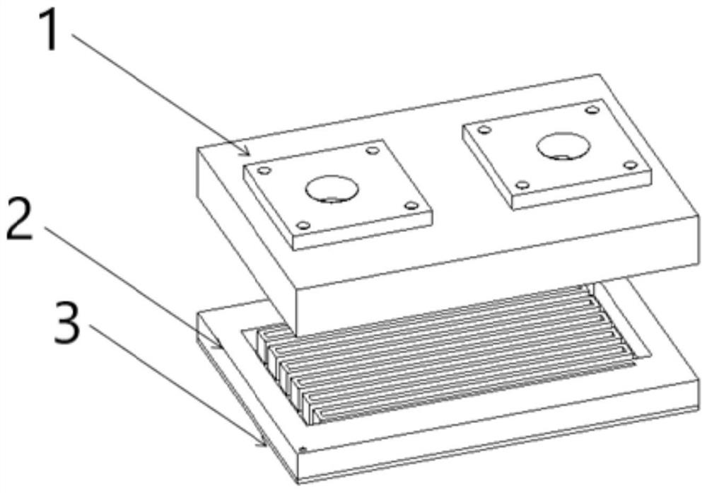
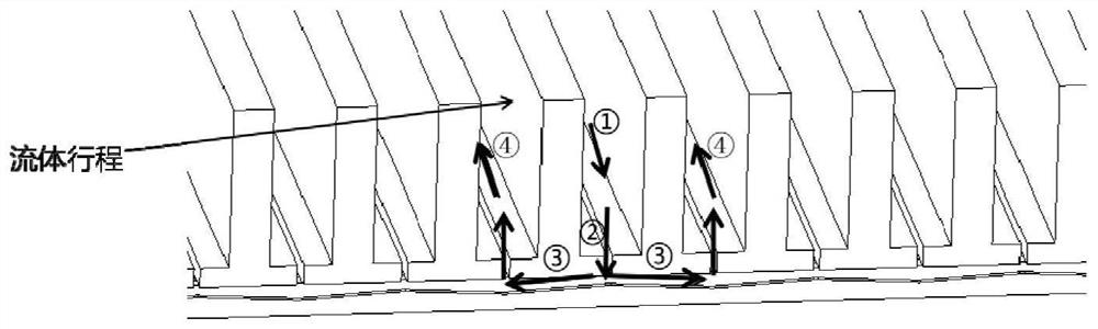
[0023] Such as figure 1 As shown, the manifold-type microchannel heat sink with a boss-like structure described in this embodiment consists of a liquid inlet layer 1, a liquid separation layer 2, and a microchannel layer 3 arranged sequentially from top to bottom, and the cooling liquid passes through the liquid inlet layer. After layer 1 enters the liquid separation layer 2, the cooling liquid is sent into the microchannel layer through the manifold splitting structure, such as figure 2 As shown, the cooling liquid enters each microchannel from t...


PUM


Abstract

The invention provides a manifold type micro-channel heat sink with a boss-like structure. The manifold type micro-channel heat sink comprises a micro-channel layer, a liquid separation layer and a liquid inlet layer, wherein the liquid separation layer is provided with an S-shaped manifold type liquid separation flow channel, a liquid inlet channel and a liquid return channel are separated, the outlet of the liquid separation layer is connected with the inlet of the micro-channel layer, after a cooling liquid enter the liquid separation layer through the liquid inlet layer and then is fed into the micro-channel layer through a manifold flow division structure, the cooling liquid enters each micro-channels through manifolds, heat exchange between fluid and crystals is completed in the micro-channels, then the fluid upwards enters a liquid return manifold through the flow path, and the cooling task is completed. According to the invention, the problem that the heat sink heat dissipation surface is low in temperature due to a manifold micro-channel heat sink micro-channel inlet impact area is solved through the ball-convex-like structure, and the temperature of the low-temperature area is adjusted by adjusting the structure size of the ball-convex-like structure, so that the purpose of uniform temperature of the heat dissipation surface is achieved; and the heat sink liquid separation layer enables the flow cooled to reach each micro-channel to be uniformly distributed, so that the temperature uniformity of the heat dissipation surface of the heat sink is further improved.

Description

technical field [0001] The invention relates to the technical field of high heat flux heat dissipation and laser crystal heat dissipation, in particular to a manifold microchannel heat sink with a boss-like structure. Background technique [0002] In recent years, high-frequency, high-energy, high-output power lasers have played a vital role in the fields of national defense (laser weapons), industrial processing and scientific research. People have also proposed higher and higher requirements for the output power and beam quality of lasers. Require. A laser crystal is a crystal material that converts the energy provided by the outside world into a highly parallel and monochromatic laser that is coherent in space and time through an optical resonator. The crystal temperature and crystal temperature uniformity will seriously affect the quality of the light output. [0003] The temperature and thermal stress of the laser crystal are different, resulting in a different refract...

Claims


Application Information

Patent Timeline
Patent Type & Authority Applications(China)
IPC IPC(8): H01S3/04H01S3/042
CPCH01S3/0407H01S3/042
Inventor 陈建辉陈宇鹏程度煦赵帅于世杰
Owner CHINA ELECTRONICS TECH GROUP CORP NO 16 INST
Why Eureka
Try Eureka