
Multi-band phased-array antenna rotation testing device

A phased array antenna and testing device technology, which is applied to the casing of the measuring device, the antenna radiation pattern, the radio wave measurement system, etc., can solve the problems of limited rotation angle around the X axis, inconvenience, and lack of the function of rotating around the Z axis, etc. Small size, easy installation, light weight effect

Inactive Publication Date: 2021-06-15
10TH RES INST OF CETC
View PDF4 Cites 0 Cited by
  • Summary
  • Abstract
  • Description
  • Claims
  • Application Information

AI Technical Summary

Problems solved by technology

[0003] Usually, the test turntable in the darkroom places the antenna under test on the Z-axis of the two-dimensional turntable for radial testing, and the rotation around the X-axis is used as a pitch, and only part of the angular rotation around the X-axis and Y-axis can be performed, and there is no rotation around the Z-axis. function, resulting in a limited rotation angle around the X-axis. If the rotation around the Y-axis is used for testing, the receiving horn needs to be installed on the roof, which is extremely inconvenient. In addition, the test around the Z-axis is the most demanding direction for antenna rotation testing. Therefore Need an antenna test device for rotating around the Z axis

Method used


Image

  • Multi-band phased-array antenna rotation testing device
  • Multi-band phased-array antenna rotation testing device
  • Multi-band phased-array antenna rotation testing device

Examples


Embodiment Construction

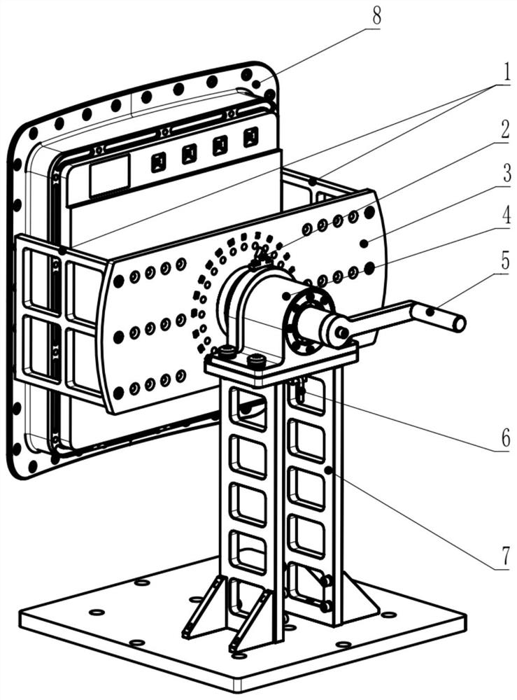
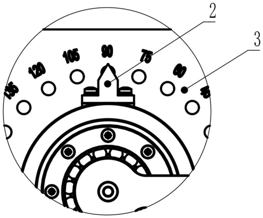
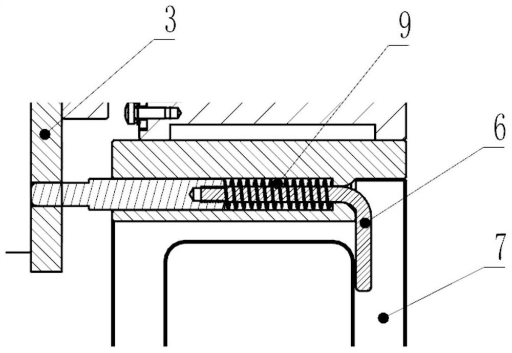
[0015] refer to Figure 1-Figure 3 . In the preferred embodiment described below, a multi-band phased array antenna rotation test device includes: the vertical plate pillar 7 fixed on the base and the bearing seat 4 on the platform thereof, and the bearing is assembled through the bearing seat 4 The connected rocker 5, the U-shaped cantilever bracket 1 axially connected by the rocker 5 through the scale plate 3 steering hole, and the antenna 8 under test fixedly connected to the two inner sides of the U-shaped cantilever bracket 1 wherein: the U-shaped cantilever bracket 1 According to the shape of the inside of the radome, it is a curved surface or a plane structure (conformal with the inside of the radome), and is fixedly connected with the scale plate 3 through the U-shaped cantilever bracket 1 to form a rotating cantilever connected to the crank handle 5; the scale plate 3 is formed with surrounding bearings The circular array indexing hole system and its indexing line di...


PUM


Abstract

A multi-band phased-array antenna rotation testing device disclosed by the invention is simple in structure, convenient to install and high in precision, and has an angle rotation control function. According to the technical scheme, a U-shaped cantilever support (1) is fixedly connected with the inner side of a radome in a conformal mode according to the shape of the inner side of the radome, and the U-shaped cantilever support is fixedly connected with a scale plate (3) to form a rotary cantilever connected with a rocking handle (5); and the scale plate is provided with a circular array indexing hole system and indexing scribed lines which are uniformly distributed around the circle center of a bearing in an equally divided manner, the rocking handle is rotated to drive a tested antenna (8) to rotate and control the steering angle of the scale plate, a pointer (2) fixed at the top end of a bearing seat (4) and coinciding with the axis indicates the rotation angle of the tested antenna (8) by using the tip, and a rotation angle locking function is achieved through an elastic indexing pin (6) mounted on the lower side of the bearing seat. The device can be adapted to different darkroom rotary tables, and meets the installation requirements of various rotary tables.

Description

technical field [0001] The invention relates to the technical field of phased array antenna testing, in particular to a rotating testing device suitable for multi-band phased array antennas. Background technique [0002] The most important difference between phased array radar and other system radars is the use of phased array antenna technology, so the test is also different. The antenna of a phased array radar consists of many antenna elements arranged in an array. This kind of radar uses a computer to control the phase shifter of the antenna array, thereby changing the phase distribution on the array, and finally forming the desired beam and scanning the beam in space according to certain rules. Phased array antennas come in many forms, such as linear arrays, planar arrays, circular arrays, cylindrical arrays, spherical arrays, and conformal arrays. The test of phased array antenna includes testing of basic characteristics such as beam pointing, beam width, antenna gain...

Claims


Application Information

Patent Timeline
IPC IPC(8): G01R29/10G01R1/04G01S7/40
CPCG01R29/10G01R1/04G01S7/4026
Inventor 杨德春
Owner 10TH RES INST OF CETC
Learn More