Dual-polarization filtering antenna unit and dual-polarization filtering antenna array

A filtering antenna and dual-polarization technology, which is applied to antenna arrays, antenna arrays, antennas, etc. that are powered separately, can solve the problems of antenna bandwidth narrowing, achieve extended low-frequency bandwidth, good band-stop filtering effect, and realize miniaturization Effect

Active Publication Date: 2021-06-15
SOUTH CHINA UNIV OF TECH
View PDF9 Cites 1 Cited by
  • Summary
  • Abstract
  • Description
  • Claims
  • Application Information

AI Technical Summary

Problems solved by technology

However, in actual design, due to the limitation of the antenna size by the application scenario of the antenna, it is often necessary to simplify the antenna structure in order to reduce the antenna size, which leads to narrowing of the antenna bandwidth.

Method used


Image

  • Dual-polarization filtering antenna unit and dual-polarization filtering antenna array
  • Dual-polarization filtering antenna unit and dual-polarization filtering antenna array
  • Dual-polarization filtering antenna unit and dual-polarization filtering antenna array

Examples


example 1

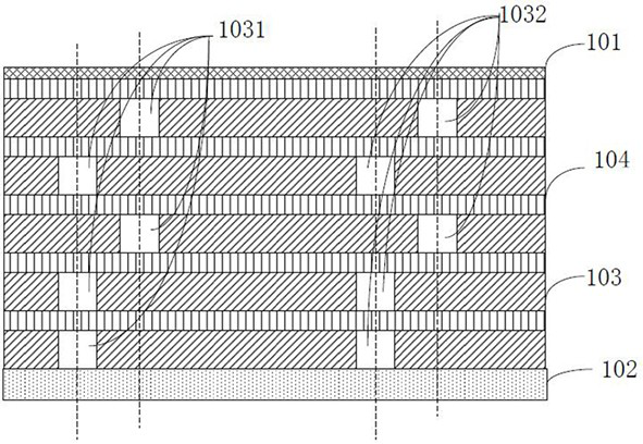
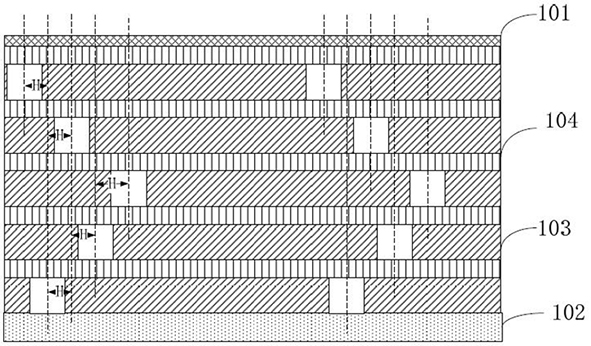
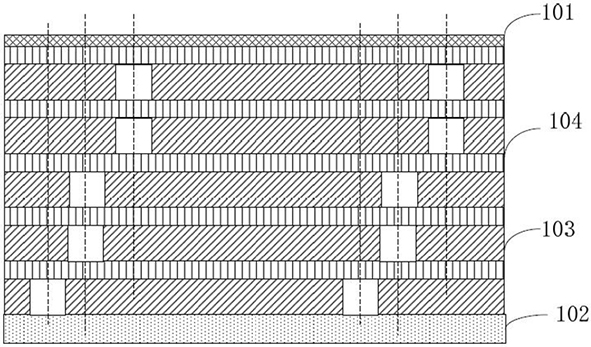
[0106] Such as Figure 16 and Figure 17 As shown, it shows a miniaturized dual-frequency dual-polarization millimeter-wave filter antenna unit, including an electric dipole structure 1, a magnetic dipole structure 2, a metallized via hole 3, a feed structure 4 and a metal substrate 5. Multiple dielectric layers are arranged between the electric dipole structure 1 and the metal substrate 5 .

[0107] Among them, such as Figure 9 As shown, the electric dipole structure 1 includes four radiating sheets 11 distributed in an array, and the structure of the radiating sheets is not limited to circular, rectangular, triangular or fan-shaped.

[0108] Such as Figure 15 and Figure 18 As shown, the magnetic dipole structure 2 includes a metal strip 22, the metal strip 22 forms a closed area, each dielectric layer is provided with a metallized via hole 3 in the area corresponding to the closed area, and the metallized via hole 3 of a plurality of dielectric layers The axes are pa...

example 2

[0124] Such as Figure 23 As shown, this embodiment provides another miniaturized dual-frequency dual-polarized millimeter-wave filter antenna, which includes an electric dipole structure 10, a magnetic dipole structure 20, short-circuit column structures 301 and 302, and a feed structure 40 and metal substrate 50.

[0125] Such as Figure 23 and Figure 24 As shown, the short-circuit column structure 302 includes a plurality of short-circuit columns connected to each other, which can be further equivalent to metal walls, distributed in four quadrants of the metal ground 50 , and distributed rotationally symmetrically around the center of the metal ground. When the antenna works in the 0° polarization direction, along the 0° polarization direction, the current flows from one side of the short-circuit column through the metal ground to the other side of the short-circuit column, resulting in resonance, thereby generating a new radiation mode at low frequencies, greatly Broad...


PUM


Abstract

The invention relates to a dual-polarization filtering antenna unit and a dual-polarization filtering antenna array, and relates to the technical field of antennas. The dual-polarization filtering antenna unit comprises a metal substrate and a radiation layer, wherein a plurality of dielectric layers are arranged between the metal substrate and the radiation layer, each dielectric layer has a first via hole and a second via hole, the first via holes and the second via holes are used for accommodating metal columns, the metal columns are used for transmitting current signals, the axes of the first via holes of the plurality of dielectric layers are parallel and are spaced at a preset distance, and the first via holes of the upper and lower adjacent dielectric layers are electrically connected through the metal layer between the upper and lower adjacent dielectric layers. According to the dual-polarization filtering antenna unit and the dual-polarization filtering antenna array of the invention, the first via holes and the second via holes are loaded, the first via holes and the second via holes are combined to generate a plurality of resonance modes, on one hand, a radiation zero point is generated in a stop band and a relatively good band elimination filtering effect is realized; and on the other hand, the low-frequency bandwidth of the antenna unit is expanded, and the miniaturization and multiband design of the antenna is realized.

Description

technical field [0001] The present application relates to the technical field of antennas, in particular to a dual-polarization filtering antenna unit and a dual-polarization filtering antenna array. Background technique [0002] The dual-frequency dual-polarization antenna is a multi-band miniaturization and dual-polarization design. The multi-frequency antenna enables the antenna to work in multiple frequency bands at the same time, so that one multi-frequency antenna can replace multiple single-frequency antennas, further improving the communication system. The level of integration meets the requirements of 5G communication systems. [0003] At present, base station antennas are developing in the direction of broadband, and the wider the bandwidth of the antenna, the larger its size. However, in actual design, limited by the application scenarios of the antenna to the size of the antenna, it is often necessary to simplify the antenna structure in order to reduce the size...

Claims


Application Information

Patent Timeline
Patent Type & Authority Applications(China)
IPC IPC(8): H01Q1/38H01Q1/36H01Q5/28H01Q5/307H01Q5/314H01Q9/04H01Q1/24H01Q21/06
CPCH01Q1/38H01Q1/36H01Q5/28H01Q5/307H01Q5/314H01Q9/0414H01Q1/246H01Q21/061
Inventor 章秀银姚树锋杨圣杰
Owner SOUTH CHINA UNIV OF TECH
Why Eureka
Try Eureka