
Solar building roof

A technology for solar buildings and roofs, applied in the field of solar buildings, can solve problems such as energy waste and environmental pollution, and achieve the effects of improving barrier effects, improving energy waste, and reducing damage

Active Publication Date: 2021-06-18
无锡北大建筑工程有限公司
View PDF12 Cites 0 Cited by
  • Summary
  • Abstract
  • Description
  • Claims
  • Application Information

AI Technical Summary

Problems solved by technology

[0005] In order to improve the problems of energy waste and environmental pollution caused by photovoltaic panel components being damaged by the external environment, this application provides a solar building roof

Method used


Image

  • Solar building roof
  • Solar building roof
  • Solar building roof

Examples


Embodiment 1

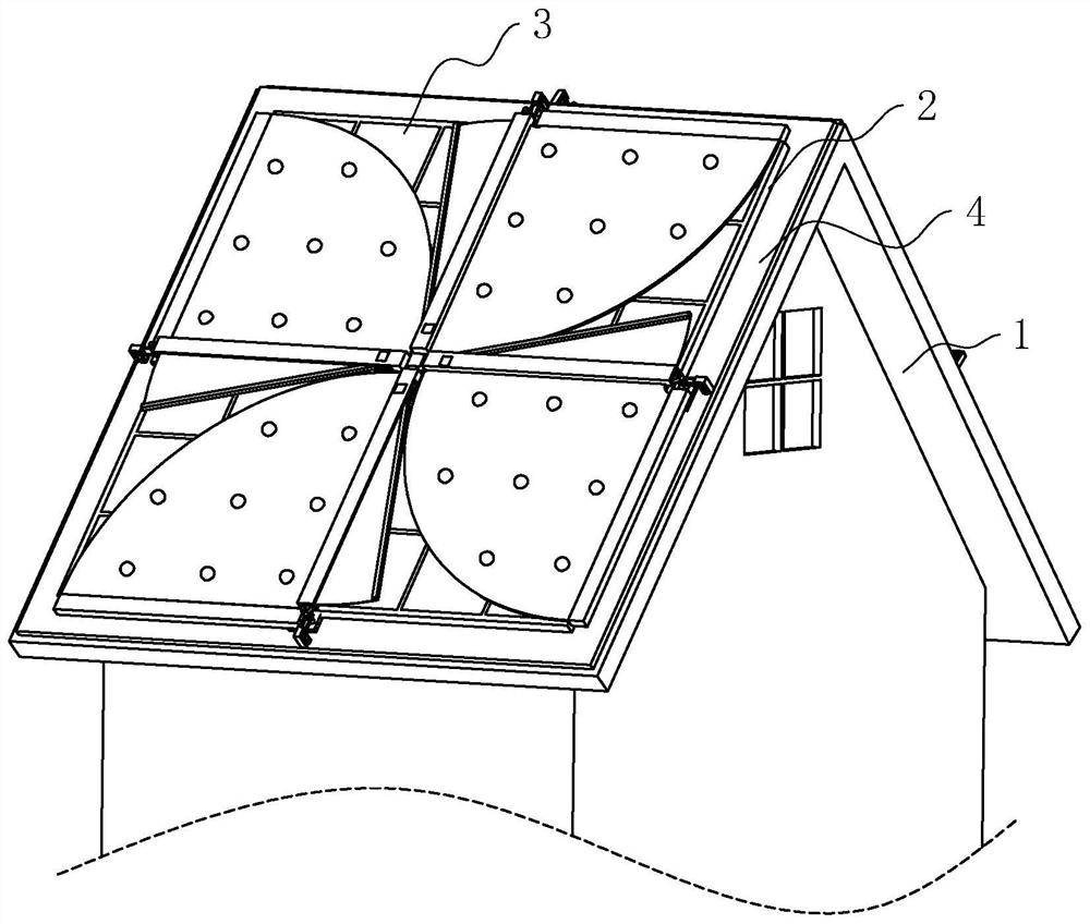
[0040] refer to figure 1 The solar building roof includes a roof body 1 , a metal frame 2 arranged on the roof body 1 , and a photovoltaic panel assembly 3 arranged on the metal frame 2 . Wherein, the roof body 1 is provided with a mounting plate 4 , and the mounting plate 4 is provided with a protection mechanism capable of protecting the photovoltaic panel assembly 3 .

[0041] refer to figure 1 , the mounting plate 4 is arranged in a rectangular shape, the surface of the mounting plate 4 is arranged in a square shape, and the mounting plate 4 is fixed and tiled on the roof body 1 .

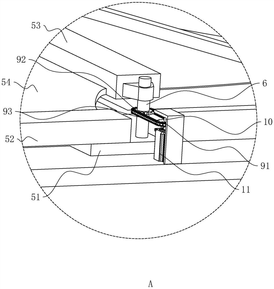
[0042] refer to figure 2 and image 3 , The protection mechanism includes a mounting base 51 , a mounting column 52 , a driving column 53 , and a cloth 54 . Wherein, the installation base 51 is arranged in a rectangular parallelepiped, and there are four installation bases 51. The four installation bases 51 are respectively located beside the four side walls of the installation plate 4, an...

Embodiment 2

[0057] refer to Figure 9 , The difference from Embodiment 1 is that the driving device includes a driving roller 94 , a driven roller 95 and a belt 96 . Wherein, the second adapter shaft 21 is rotatably connected to the mounting plate 4 , and the second adapter shaft 21 is arranged along a direction perpendicular to the surface of the mounting plate 4 , and the driving roller 94 is fixedly connected to the second adapter shaft 21 . The driven roller 95 is fixedly connected to the rotating shaft 6 , and the chain 93 is sleeved on the driving roller 94 and the driven roller 95 .

[0058] The mounting plate 4 is fixedly connected with the drive motor 2 22, and the output shaft of the drive motor 2 22 is fixedly connected with the adapter shaft 2 21 through a coupling.

[0059] The implementation principle of embodiment 2 is: when it is necessary to drive the driving column 53 to rotate, start the driving motor 22, the driving motor 22 drives the driving roller 94 to rotate, and...


PUM


Abstract

The invention relates to a solar building roof, and relates to the field of solar buildings. The solar building roof comprises a roof body, a metal frame arranged on the roof body and a photovoltaic panel assembly arranged on the metal frame, wherein a mounting plate is arranged on the roof body; the metal frame is fixedly connected to the mounting plate; a plurality of protection mechanisms are fixedly connected to the mounting plate; each protection mechanism comprises a mounting base, a mounting column, a driving column and a first blocking cloth; the mounting columns are fixedly connected with the mounting bases; the driving columns are rotationally connected with the mounting bases; the driving columns and the mounting columns are arranged in the direction parallel to the plate surface of the mounting plate; the first blocking cloths are fixedly connected between the driving columns and the mounting columns; the first blocking cloths can rotationally shield the upper part of the photovoltaic panel assembly; and a driving device used for driving the driving columns to rotate is arranged on the mounting plate. The solar building roof has the effects that the problems of energy waste and environmental pollution caused by the fact that the photovoltaic panel assembly is damaged by the external environment can be solved.

Description

technical field [0001] The present application relates to the field of solar buildings, in particular to solar building roofs. Background technique [0002] The solar roof is to install a solar power generation device on the top of the house, and use solar photovoltaic technology to generate electricity in the urban and rural building fields, so as to achieve the goal of energy saving and emission reduction. In order to implement China's energy-saving and emission-reduction goals promised to the world, and strengthen policies to support the new energy economy strategy, relevant national ministries and commissions have launched a solar roof plan. [0003] In the related art, the Chinese patent with the notification number CN104018627B discloses a solar building roof, which includes a metal frame erected on the roof beams. The frame includes a rectangular frame, and the rectangular frame is divided into a series of grids by beams and longitudinal beams; Rectangular frames, be...

Claims


Application Information

Patent Timeline
Patent Type & Authority Applications(China)
IPC IPC(8): E04D13/00E04D13/18E04B1/98H02S20/23H02S40/00F16F15/023
CPCE04D13/00E04B1/98H02S20/23H02S40/00F16F15/0232Y02E10/50Y02B10/10
Inventor 唐芳勇陈静芝
Owner 无锡北大建筑工程有限公司
Learn More