
Rapid centering optical element center thickness precision measuring instrument

A technology of optical components and center thickness, which is applied in the field of optical precision measurement, can solve the problems of high cost, complex structure, and easy damage of the surface, and achieve the effect of high-precision measurement and simple structure

Pending Publication Date: 2021-06-18
西安应用光学研究所
View PDF0 Cites 0 Cited by
  • Summary
  • Abstract
  • Description
  • Claims
  • Application Information

AI Technical Summary

Problems solved by technology

[0003] Optical lenses are made of glass or polymer materials, and the surface is easily damaged. In the traditional contact center thickness measurement, frequent contact will affect the surface finish of the lens. In order to solve the above problems, experts and scholars in the field of optical engineering have proposed several non-destructive Measurement method, the published literature mainly includes: "Design of Lens Center Thickness Measuring Instrument" in "Journal of Xi'an University" in 2003, which introduced a technical solution for measuring the thickness of the lens center by interferometry, although the accuracy of the interferometry itself is It is relatively high, but it is easily affected by environmental factors such as external airflow and vibration. In addition, the structure of this method is relatively complicated and the cost is high. In 2011, "Design of Lens Thickness Measurement System Based on Confocal Method" in "Journal of Instrumentation" , this document uses white light as the confocal light source, and uses the spectral information reflected back from the upper and lower surfaces of the measured lens to calculate the thickness of the lens

Method used


Image

  • Rapid centering optical element center thickness precision measuring instrument
  • Rapid centering optical element center thickness precision measuring instrument

Examples


Embodiment Construction

[0012] In order to make the purpose, content and advantages of the present invention clearer, the specific implementation manners of the present invention will be further described in detail below in conjunction with the accompanying drawings and embodiments.

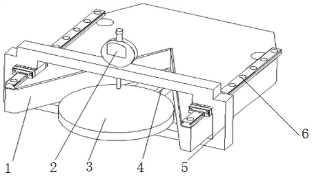
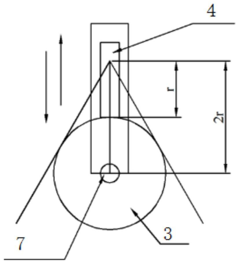
[0013] refer to figure 1 and figure 2 As shown, the optical element center thickness measuring instrument of this embodiment includes an angle plate bottom plate 1, a meter head bracket 5, a measuring ruler 4, and a meter head bracket guide rail 6; one end of the angle plate bottom plate 1 is provided with a V-shaped opening groove with a vertex angle of 60° , the lens 3 to be tested is placed at the V-shaped opening groove and is tangent to the two sides of the V-shaped opening groove; It is a rectangular frame, which is set on the bottom plate of the angle plate. The two sides of the top frame of the gauge bracket 5 cooperate with the gauge bracket guide rail 6 and can slide back and forth along the gauge bracket gu...


PUM


Abstract

The invention discloses a rapid centering optical element center thickness precision measuring instrument. The measuring instrument comprises an angle plate bottom plate with one end provided with a V-shaped open slot with a vertex angle of 60 degrees, and a lens to be measured is placed in the V-shaped open slot; a guide rail is arranged on the upper surface of the angle plate bottom plate, a gauge outfit support slides in a reciprocating mode along a gauge outfit support guide rail, a micrometer gauge outfit is arranged on the gauge outfit support, and when the gauge outfit support slides in a reciprocating mode, the micrometer gauge outfit moves in the direction of the vertex angle bisector of the V-shaped open slot; a measuring scale is further arranged at the bottom of the angle plate bottom plate and is arranged in the direction of the vertex angle bisector of the V-shaped open slot; the gauge outfit support and the measuring scale move in the same direction, and the speed ratio is 2: 1; at the beginning, the measuring scale and the gauge outfit support are both located at the vertex position of the V-shaped open slot, when the measuring scale moves to make contact with the lens to be measured, the moving distance of the measuring scale is the radius r of the lens to be measured, at the moment, the moving distance of the micrometer gauge outfit on the gauge outfit support is 2r, and the measuring scale is located above the center of the lens to be measured. The measuring instrument can be suitable for high-efficiency and high-precision measurement of the center thickness of various circular optical elements with different radiuses.

Description

technical field [0001] The invention belongs to the technical field of optical precision measurement, and relates to a fast centering precision measuring instrument for the center thickness of an optical element. Background technique [0002] As a basic parameter of the lens, the central thickness is a key parameter affecting the imaging quality of the high-precision optical imaging lens, and must be effectively measured during the processing. [0003] Optical lenses are made of glass or polymer materials, and the surface is easily damaged. In the traditional contact center thickness measurement, frequent contact will affect the surface finish of the lens. In order to solve the above problems, experts and scholars in the field of optical engineering have proposed several non-destructive Measurement method, the published literature mainly includes: "Design of Lens Center Thickness Measuring Instrument" in "Journal of Xi'an University" in 2003, which introduced a technical sol...

Claims


Application Information

Patent Timeline
IPC IPC(8): G01B5/06
CPCG01B5/06
Inventor 王芝蔡锦浩谢国兵付晓庆翁锴强张永宁黄玉张明韩俊王慧娜薛永刚冯攀马彰鑫
Owner 西安应用光学研究所
Features
  • Generate Ideas
  • Intellectual Property
  • Life Sciences
  • Materials
  • Tech Scout
  • Unparalleled Data Quality
  • Higher Quality Content
  • 60% Fewer Hallucinations
Learn More