Distributed power transformer winding state monitoring method and system based on vibration method
A transformer winding and distributed power technology, applied in the field of distributed power transformer winding state monitoring, can solve problems such as vibration signal asynchrony, vibration signal distortion, sampling omission, etc., to avoid amplitude attenuation and electromagnetic interference, system coupling degree Low, guaranteed synchronization effect
- Summary
- Abstract
- Description
- Claims
- Application Information
AI Technical Summary
Problems solved by technology
Method used
Image

Examples
Embodiment Construction
[0089] The application will be further described below in conjunction with the accompanying drawings. The following examples are only used to illustrate the technical solutions of the present invention more clearly, but not to limit the protection scope of the present application.
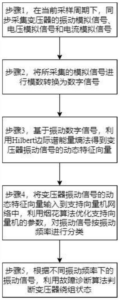
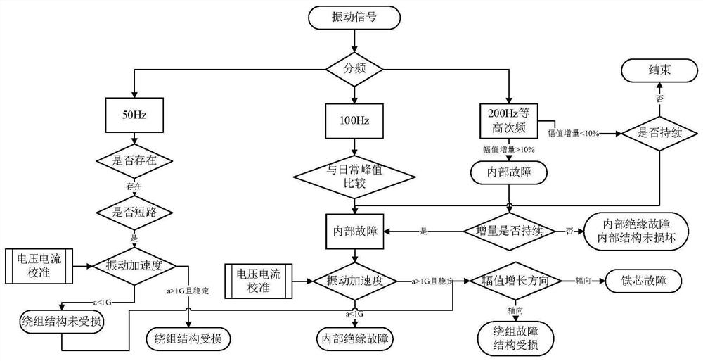
[0090] Such as figure 1 , the steps of the distributed power transformer winding state monitoring method based on the vibration method are as follows:
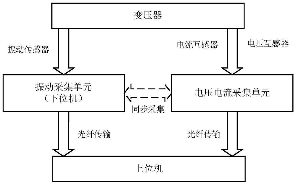
[0091] Step 1, under the current sampling period, synchronously collect vibration analog signals, voltage analog signals and current analog signals of the transformer.
[0092] specifically,
[0093] In step 1, the vibration simulation signal is the vibration amplitude simulation signal and vibration acceleration simulation signal at different positions of the transformer oil tank wall; the voltage simulation signal and current simulation signal are the voltage simulation signal and current simulation signal at the secondary terminal of the trans...
PUM
 Abstract
Description
Claims
Application Information
 - Generate Ideas
- Intellectual Property
- Life Sciences
- Materials
- Tech Scout
- Unparalleled Data Quality
- Higher Quality Content
- 60% Fewer Hallucinations
Browse by: Latest US Patents, China's latest patents, Technical Efficacy Thesaurus, Application Domain, Technology Topic, Popular Technical Reports.
© 2025 PatSnap. All rights reserved.Legal|Privacy policy|Modern Slavery Act Transparency Statement|Sitemap|About US| Contact US: help@patsnap.com