Ka-band one-to-eight microstrip fan-shaped power divider

A power divider and ka-band technology, used in satellite communications, navigation, and microwave communications.

Pending Publication Date: 2021-06-18
10TH RES INST OF CETC
View PDF6 Cites 0 Cited by
  • Summary
  • Abstract
  • Description
  • Claims
  • Application Information

AI Technical Summary

Problems solved by technology

3. Due to the longer quarter wavelength, the occupied area is too large
Since the signal transmitted by the transmitter may exceed hundreds of watts or even several kilowatts, it is very likely that the leaked transmitted signal will leak into the receiver through the antenna, circulator or switch, even if only a small part of the power leaks, It is also possible to burn out the LNA

Method used


Image

  • Ka-band one-to-eight microstrip fan-shaped power divider
  • Ka-band one-to-eight microstrip fan-shaped power divider
  • Ka-band one-to-eight microstrip fan-shaped power divider

Examples


Embodiment Construction

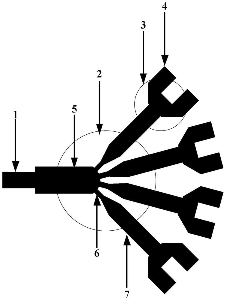
[0018] refer to figure 1 . In the preferred embodiment described below, a Ka-band one-to-eight microstrip fan-shaped power splitter includes: a one-to-four power splitter 2 composed of an impedance converter 5 connected to the input microstrip line 1, wherein: At least three high-impedance microstrip lines 6 distributed in fan-shaped branches are distributed on the arc surface of the impedance converter 5, and the impedance matching microstrip lines 7 connected to the same body are integrated with the impedance matching microstrip lines 7 triangular cup-shaped microstrips The connected wide-body microstrip line is connected with a trapezoidal fork-shaped one-to-two power splitter 3, and the fork-shaped T-shaped joint 4 is used as the output microstrip line, thereby forming a fan-shaped distribution evenly distributed on the soft substrate. Ka-band one-to-eight microstrip fan-shaped power splitter with branch distribution.

[0019] All transmission lines are microstrip lines,...


PUM


Abstract

A Ka-band one-to-eight microstrip fan-shaped power divider disclosed by the invention is compact in structure, wide in frequency band, good in standing-wave ratio, small in insertion loss and good in phase consistency. According to the technical scheme, an impedance converter (5) connected through an input microstrip line (1) is adopted to form a one-to-four power divider (2), and at least three high-impedance microstrip lines (6) distributed in a fan-shaped branch knot mode and impedance matching microstrip lines (7) integrally connected with the high-impedance microstrip lines (6) are distributed on the arc face of the impedance converter. A wide-body microstrip line integrally connected with the triangular cup-shaped microstrip of each impedance matching microstrip line is connected with a one-to-two power divider (3) in a trapezoidal fork ear shape, and a fork ear-shaped T-shaped section (4) is used as an output microstrip line, so that the Ka-band one-to-eight microstrip fan-shaped power divider which is uniformly distributed on the soft substrate and is in fan-shaped branch knot distribution is formed. Compared with a traditional power divider, the power divider in the form is small in consumption and large in power capacity, and the energy loss at the joint is remarkably reduced.

Description

technical field [0001] The invention relates to the fields of microwave communication, navigation and satellite communication, and can be widely used in the power splitter of the low-noise receiving front end of a millimeter-wave high-power receiver. Background technique [0002] In a microwave system, the transmitting power needs to be distributed to the transmitting unit in a certain proportion, so the power divider is widely used in the microwave system. Its performance directly affects the energy distribution and synthesis efficiency of the entire system. Since the input-to-output power ratio of the traditional power splitter is fixed, it cannot meet the needs of high-resolution MR-EPT imaging. The power divider is the abbreviation of the power divider. It is a kind of energy that divides one input signal into two or multiple outputs with equal or unequal energy, similar to a microstrip wave passive device; it can also conversely divide the energy of multiple signals S...

Claims


Application Information

Patent Timeline
Patent Type & Authority Applications(China)
IPC IPC(8): H01P5/16
CPCH01P5/16
Inventor 张丽娟黄建何毅龙裴乃昌
Owner 10TH RES INST OF CETC
Why Eureka
Try Eureka