
Drying air duct system of drying equipment

A drying equipment and air duct technology, applied in the field of drying equipment, can solve the problems of low energy utilization rate, exhaust waste heat waste, and increase drying cost, so as to improve energy utilization rate, improve heat exchange efficiency, and avoid heat loss Effect

Inactive Publication Date: 2021-06-22
常州市茂宏干燥设备有限公司
View PDF1 Cites 2 Cited by
  • Summary
  • Abstract
  • Description
  • Claims
  • Application Information

AI Technical Summary

Problems solved by technology

[0003] In the traditional shiitake drying process, the gas is heated to the required temperature by burning wood, and then the high-temperature gas is sent into the drying chamber by a fan or an air pump to heat the shiitake mushrooms in the drying chamber. The consumption is large, the drying cost is increased, and it will pollute the environment and many other shortcomings
[0004] In order to solve the above problems, the patent of patent application publication number CN209017859U discloses a drying air duct system of drying equipment. Figure 5 , this application can not only reduce energy consumption and reduce drying cost; but also can effectively improve the heating uniformity of the mushroom cover edge during the drying process, and avoid the uneven heating of the mushroom cover edge, which will cause the dry cover edge of the mushroom to sag. Uneven inward rolling affects the quality of dried shiitake mushrooms
[0005] But above-mentioned technical scheme still has many shortcomings when practical application;
[0006] 1. Since the drying air duct system uses an independent heating chamber and drying chamber, the heating chamber heats the outside air, and then transports the high-temperature air to the drying chamber through the circulation structure to dry the materials. The high-temperature gas During the transfer process, a large amount of heat is lost, resulting in low energy utilization, and the lower temperature gas enters the drying chamber, which greatly reduces the drying efficiency, so the energy consumption is extremely high, and there are defects;
[0007] 2. Since the drying air duct system directly transports the dried gas to the outside of the system in order to reduce the humidity of the internal environment of the system, the gas after drying and utilization still has some waste heat, and the direct discharge of waste heat is directly wasted, so Less environmentally friendly, and fresh incoming outside air is drier but cooler and requires a lot of energy to reheat

Method used


Image

  • Drying air duct system of drying equipment
  • Drying air duct system of drying equipment
  • Drying air duct system of drying equipment

Examples


Embodiment approach

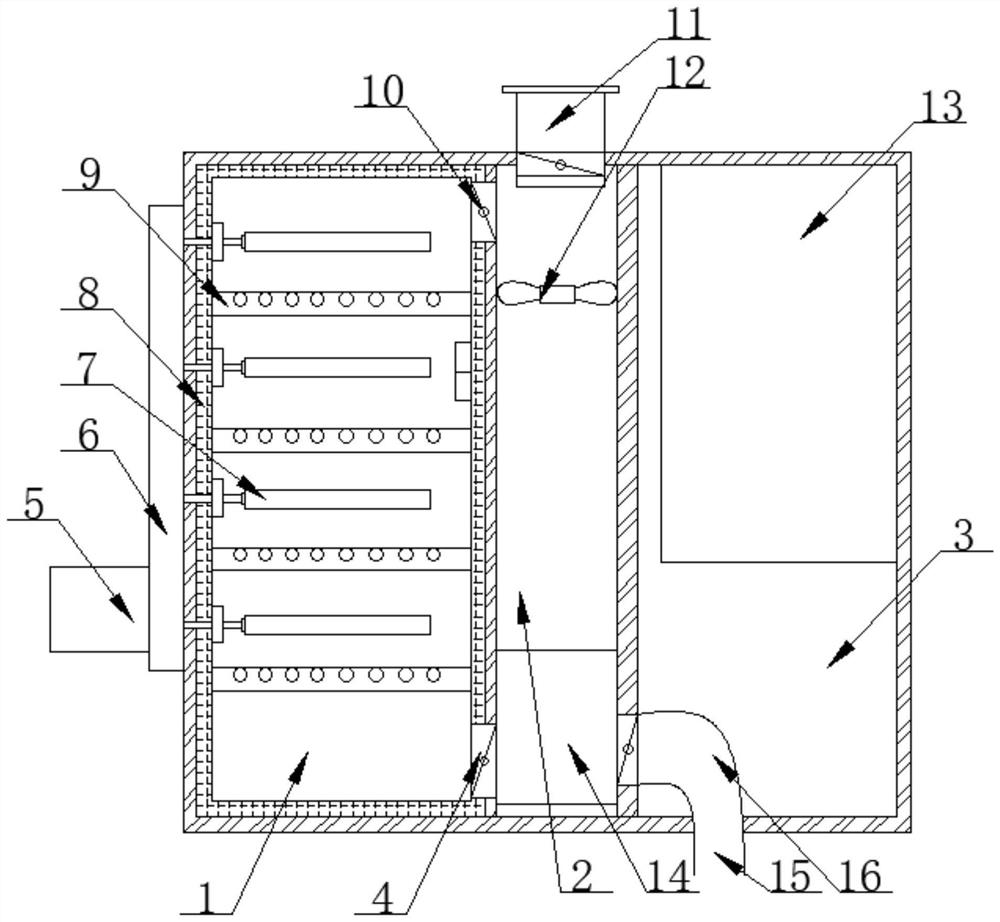
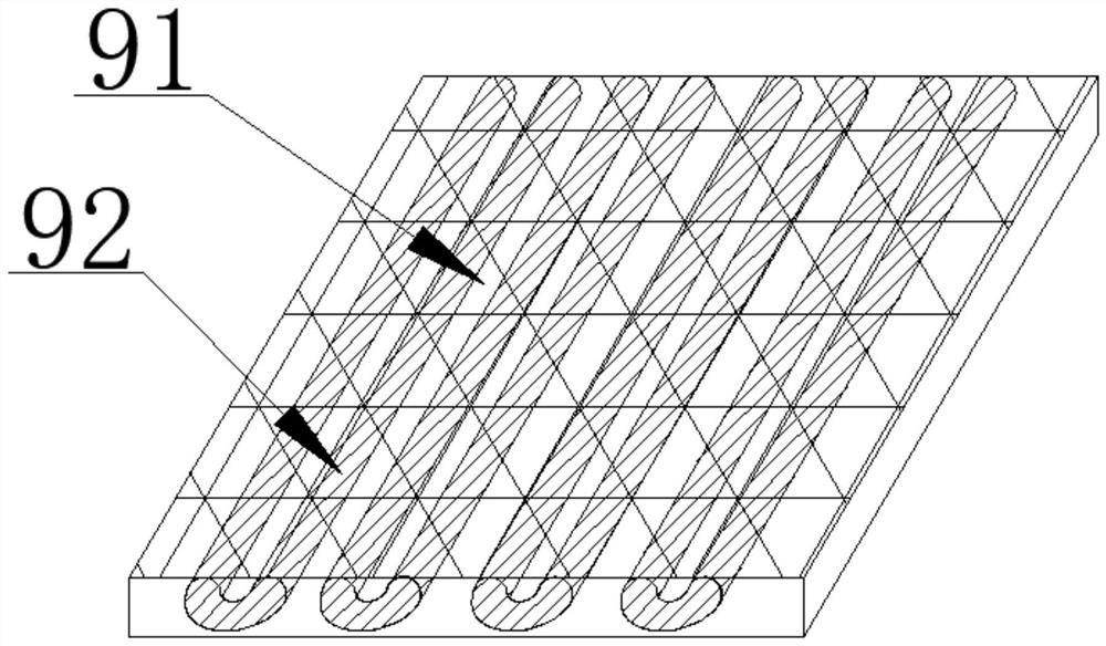
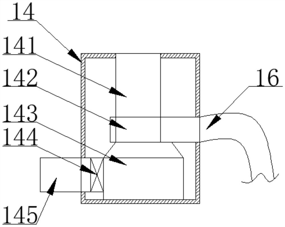
[0028] The implementation mode is as follows: by optimizing the structural layout, the heating device and the storage plate 91 are integrated in the drying chamber 1, and the heating pipe 92 is used to directly heat the gas in the drying chamber 1, so that the environment in the drying chamber 1 can be rapidly heated. Heat up, and cooperate with the insulation layer 8 to carry out continuous drying, avoid heat loss caused by traditional heating, drying and separation, improve energy utilization, and have higher drying efficiency and improve production efficiency; in addition, the present invention uses plate heat exchange The device 142 improves the heat exchange efficiency, uses the cooled external cold air to lower the temperature of the high-temperature humid air, condenses the high-temperature humid air to recover moisture, and at the same time increases the temperature of the cold air to obtain dry cold air without additional refrigeration system cooling The high-temperatu...


PUM


Abstract

The invention discloses a drying air duct system of drying equipment, and particularly relates to the field of the drying equipment. The drying air duct system comprises a drying chamber, a desiccation chamber and an evaporator chamber, wherein a drying chamber air inlet and a drying chamber air outlet are formed in one side of the drying chamber; a transmission box and a motor box are mounted on one side of the drying chamber; the inner wall of the drying chamber is lined with a thermal insulation layer; drying nets are mounted inside the drying chamber; an indoor unit and a dehumidifier are mounted inside the desiccation chamber; an air exhaust opening is formed in the top end of the desiccation chamber; and an outdoor unit and a fresh air duct are mounted inside the evaporator chamber. The drying air duct system of the drying equipment has the advantages of improving the heat exchange efficiency by virtue of a plate heat exchanger, reducing the temperature of high-temperature humid air by virtue of cooled external cold air, condensing the high-temperature humid air to recover moisture and increasing the temperature of the cold air at the same time to obtain dry cold air, eliminating the need for an additional cooling system for cooling the high-temperature humid air and the need for an additional heat source for heating the cold air, realizing self-heating, fully realizing comprehensive utilization of energy, and achieving the purposes of environmental protection and energy conservation.

Description

technical field [0001] The invention relates to the technical field of drying equipment, and more specifically, the invention is a drying air duct system of the drying equipment. Background technique [0002] Drying equipment refers to the combination of a series of mechanical equipment to dry the moisture on the surface of objects or other liquids through certain technical means. The current popular drying technologies are mainly ultraviolet drying, infrared drying, electromagnetic drying and hot air drying. They have their own characteristics and are widely used in the drying of various mechanical equipment and food. [0003] In the traditional shiitake drying process, the gas is heated to the required temperature by burning wood, and then the high-temperature gas is sent into the drying chamber by a fan or an air pump to heat the shiitake mushrooms in the drying chamber. The consumption is large, the drying cost is increased, and the environment will be polluted and many...

Claims


Application Information

Patent Timeline
Patent Type & Authority Applications(China)
IPC IPC(8): F26B9/06F26B21/00F26B21/08F26B25/00F26B25/18
CPCF26B9/06F26B21/001F26B21/004F26B21/086F26B25/00F26B25/18
Inventor 汤永红
Owner 常州市茂宏干燥设备有限公司
Learn More