
Lens protection equipment of metal 3D printer

A technology of 3D printer and protection equipment, applied in the field of 3D printing, can solve the problems of lens explosion, powder pollution, insufficient power, etc., and achieve the effect of preventing black smoke pollution, good sealing performance, and improving practicability

Inactive Publication Date: 2021-06-25
FOSHAN FOWEI PRECISION MACHINERY +2
View PDF4 Cites 0 Cited by
  • Summary
  • Abstract
  • Description
  • Claims
  • Application Information

AI Technical Summary

Problems solved by technology

A very serious consequence of black smoke is that it will pollute the lens, especially when scanning at low speed, the laser energy input is large, and the amount of black smoke generated is also large. The power attenuation is serious when passing through the lens, and the lens will heat up quickly, become hot or even burst. The pollution of the lens by black smoke will also cause insufficient power when the laser is incident on the powder, and the powder will not melt sufficiently.
Another hazard of black smoke is: part of the black smoke falls to the surface of the unprocessed metal powder and mixes with the powder, polluting the powder and affecting the laser processing process
[0004] In order to ensure the normal use of the lens, the current metal 3D printer has to manually clean the black smoke on the lens every once in a while. Cause serious consequences such as lens explosion

Method used


Image

  • Lens protection equipment of metal 3D printer
  • Lens protection equipment of metal 3D printer
  • Lens protection equipment of metal 3D printer

Examples


Embodiment

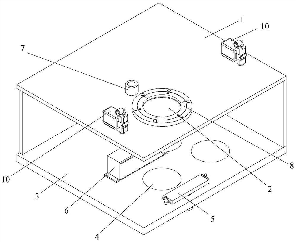
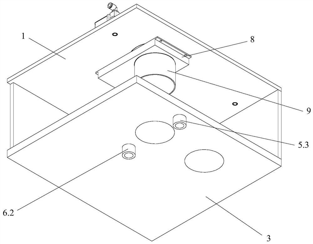
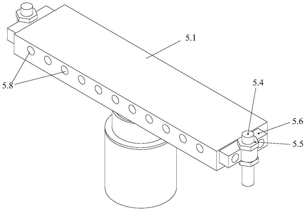
[0043] like Figure 1 to Figure 6 As shown, the lens protection device of the metal 3D printer of the present invention is arranged on the molding chamber, the top plate 1 of the molding chamber is provided with a lens 2, and the bottom plate 3 of the molding chamber below the lens 2 is used as the molding surface 4 of the lens; the lens protection The equipment includes a blower (not shown), a bottom air intake mechanism 5, a solenoid valve 10 for respectively controlling argon and exhaust, an exhaust mechanism 6 for inhaling and purifying polluted gases, and a lens protection mechanism, wherein , The lens protection mechanism includes a top air intake pipe 7, a lens protection device 8 and a guide cylinder 9 connected in sequence. The lens protector 8 is connected with the lens 2, the top air inlet pipe 7 is arranged on the top plate 1 of the molding chamber, the bottom air inlet mechanism 5 and the exhaust mechanism 6 are all arranged on the bottom plate 3 of the molding ch...


PUM


Abstract

The invention provides lens protection equipment of a metal 3D printer. The lens protection equipment is arranged on a forming chamber and comprises an air blower, a bottom air inlet mechanism, an electromagnetic valve, an exhaust mechanism used for sucking and purifying pollution gas and a lens protection mechanism. The lens protection mechanism comprises a top air inlet pipe, a lens protection device and a guide cylinder which communicate in sequence. The lens protection device is connected with a lens, and the top air inlet pipe is arranged on a top plate of the forming chamber. The bottom air inlet mechanism and the exhaust mechanism are both arranged on a bottom plate of the forming chamber, and the bottom air inlet mechanism and the exhaust mechanism are located on the two sides of a forming face and are oppositely arranged. The air outlet end of the air blower is separately connected with the bottom air inlet mechanism and the top air inlet pipe, the air inlet end of the air blower is connected with the exhaust mechanism, so that circulating air flow is formed in the forming chamber, and pollution gas formed by gasification of the lens forming in the forming chamber is purified. According to the lens protection equipment of the metal 3D printer, black smoke can be removed in time, the lens can be effectively prevented from being polluted by the black smoke, so that the practicability is improved.

Description

technical field [0001] The invention relates to the technical field of 3D printing, and more specifically, relates to a lens protection device for a metal 3D printer. Background technique [0002] 3D printing technology makes solid parts by accumulating materials layer by layer. Compared with traditional manufacturing methods, 3D printing technology has a short production cycle, no tools, molds, and can process parts with complex shapes. SLM (Selective Laser Melting) technology uses high-energy laser beams to irradiate metal powder to make it melt quickly and cool and solidify into shape. The compactness of the processed parts is close to 100%. Metal 3D printing technology has been used in automobiles, aerospace, medical, and military industries. and other fields have been widely used. [0003] When the metal 3D printer is working, the laser scans the metal powder, and the carbon elements, low melting point alloy elements and impurity elements contained in the metal powder ...

Claims


Application Information

Patent Timeline
Patent Type & Authority Applications(China)
IPC IPC(8): B22F12/70B22F12/41B22F10/28B33Y30/00B08B15/04
CPCB33Y30/00B08B15/04
Inventor 罗有旺罗烁鑫易建豪梁翱许冠毛卫东
Owner FOSHAN FOWEI PRECISION MACHINERY
Learn More