Simulation method for reflecting polarized light by underwater target based on bidirectional reflection theory

An underwater target and two-way reflection technology, applied in the field of underwater optical imaging, can solve problems such as insufficient prior knowledge

Inactive Publication Date: 2021-06-25
NORTHWESTERN POLYTECHNICAL UNIV
View PDF0 Cites 5 Cited by
  • Summary
  • Abstract
  • Description
  • Claims
  • Application Information

AI Technical Summary

Problems solved by technology

[0006] Therefore, it is necessary to provide a simulation method for the simulation analysis of underwater photon sca

Method used


Image

  • Simulation method for reflecting polarized light by underwater target based on bidirectional reflection theory
  • Simulation method for reflecting polarized light by underwater target based on bidirectional reflection theory
  • Simulation method for reflecting polarized light by underwater target based on bidirectional reflection theory

Examples


Embodiment 1

[0134] Embodiment 1 effectiveness test

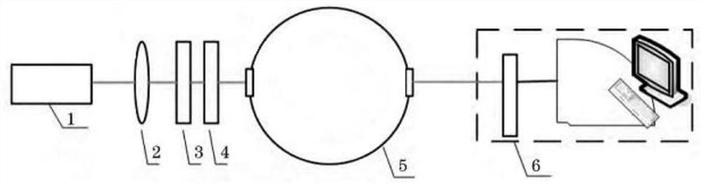
[0135] In order to verify the reliability of the simulation model of the present invention, the present invention simulates the experimental environment in the paper "Influence of Smoke Concentration on the Transmission Characteristics of Polarized Light" by Zhang Su et al., and compares the simulation and experimental results. In the paper, the experimental principle is as follows figure 1 As shown, the light emitted by the laser is attenuated by the attenuation plate, and then polarized by the polarizer. By adjusting the angle of the polarizer, different linearly polarized light can be generated. The 1 / 4 wave plate is used to generate circularly polarized light. According to It needs to be rotated in or out of the optical path at any time. The polarized light passes through the smoke simulation environment, and the bituminous coal particles are burned in the smoke simulation environment, and the particle concentration in the smoke env...

Embodiment 2

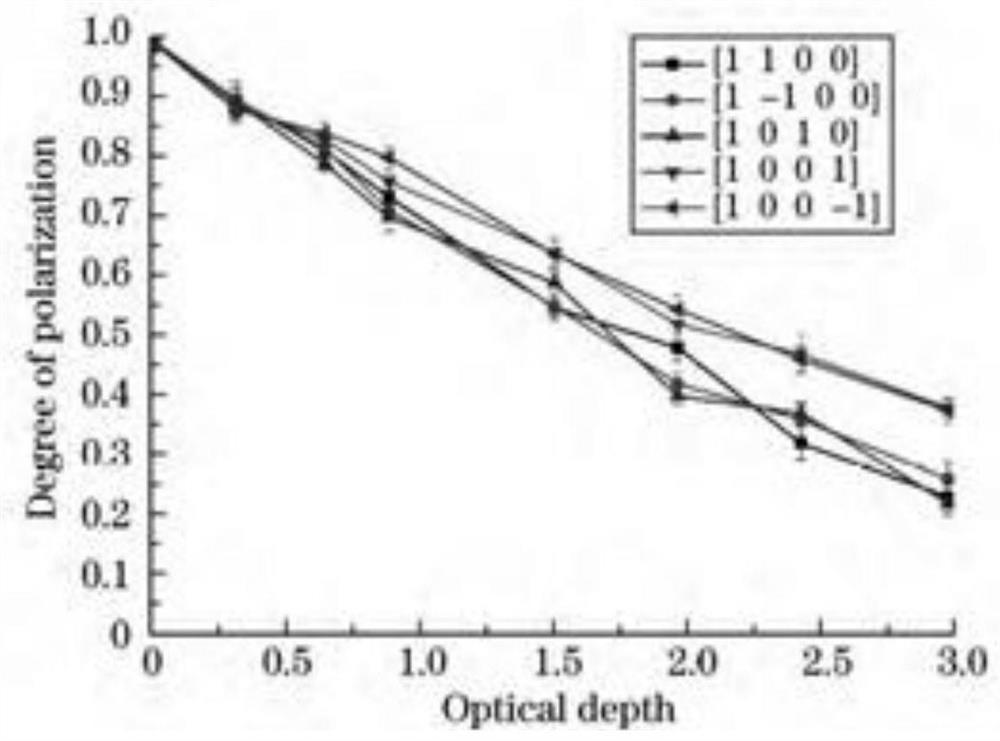
[0140] In order to analyze the polarization difference imaging of the target using linearly polarized light under the same scattering environment, the simulation model of the present invention is used to conduct experiments on the variation of the polarization degree distinction between backscattered light and target reflected light as the optical thickness changes. The total number of photons emitted is 10 6 1, emission source frequency 532nm, Gaussian laser beam emission half-angle 0.0015 / 2 and beam width 0.001, emission photon Stokes vector is linearly polarized light S 0 =[1 1 0 0], the number of scattering particles per unit volume in the underwater environment is 10 9 , particle radius 2 μm, complex refractive index m=1.52-0.001i, optical thickness 1, reflective surface roughness 0.2, reflective material refractive index 1.46, reflective material absorption coefficient 1.32 reflective material reflective coefficient 0.052. Simulation results such as Figure 6 shown.

...


PUM

PropertyMeasurementUnit
Complex refractive indexaaaaaaaaaa

Abstract

The invention provides a simulation method for reflecting polarized light by an underwater target based on a bidirectional reflection theory, and solves the problems of limitation and insufficient priori knowledge for different environments due to the fact that priori knowledge is obtained and an image is restored through an experiment mode based on a specific environment at present. The method includes the steps of 1) setting parameters of an initial light source, a scattering environment and a reflection target; 2) sampling an initial photon coordinate, a motion vector and a Stokes vector according to the initial light source parameters; and calculating an attenuation coefficient, a scattering coefficient and a single albedo according to the scattering environment parameters; 3) simulating photon movement, and sampling photon movement step length and energy weight; 4) judging photon behaviors according to the photon movement step length and the energy weight; 5) calculating the stokes vector of the finally received photon according to the motion vector of the received photon; and 6) carrying out statistical analysis on the finally received photons to obtain analysis results of photon transmission characteristics and polarization characteristics under set environmental parameters.

Description

technical field [0001] The invention belongs to the technical field of underwater optical imaging, and in particular relates to a simulation method for reflecting polarized light of an underwater target based on the two-way reflection theory. Background technique [0002] Underwater optical imaging technology uses blue and green lasers with strong penetrating ability to sea water instead of sound waves for communication or detection activities. The underwater imaging system model is as follows: emit photons—photon transmission—target reflection—photon transmission—receive photons. Underwater optical imaging has the advantages of intuitive target detection, high imaging resolution, and high information content. As an emerging technology, it complements acoustic imaging methods and plays an important role in underwater imaging detection. [0003] However, due to the water medium and underwater scattering particles such as sediment, algae and other suspended particles, the siz...

Claims


Application Information

Patent Timeline
IPC IPC(8): G01J4/00G01J11/00G01S7/497
CPCG01J4/00G01J11/00G01S7/497
Inventor 程谦王英民牛奕龙陶林伟王成王奇诸国磊郑琨
Owner NORTHWESTERN POLYTECHNICAL UNIV
Why Eureka
Try Eureka