Ultra-wide-angle lens and imaging equipment

An ultra-wide-angle lens and lens technology, applied in the field of imaging lenses, can solve the problems of low lens resolution, small field of view, obvious chromatic aberration, etc., and achieve high-definition resolution, compensating for focus shift, and good aberration correction effects.

Active Publication Date: 2021-06-25
合肥联创光学有限公司
View PDF5 Cites 5 Cited by
  • Summary
  • Abstract
  • Description
  • Claims
  • Application Information

AI Technical Summary

Problems solved by technology

[0004] However, most automotive lenses currently on the market generally have problems such as small field of view (less than 160°), low lens r...

Method used


Image

  • Ultra-wide-angle lens and imaging equipment
  • Ultra-wide-angle lens and imaging equipment
  • Ultra-wide-angle lens and imaging equipment

Examples


no. 1 example

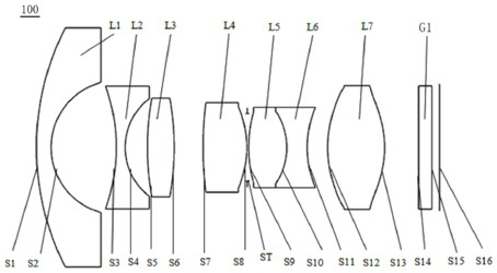
[0090] see figure 1 , which is a schematic structural diagram of the ultra-wide-angle lens 100 provided in the first embodiment of the present invention, the ultra-wide-angle lens 100 includes in sequence from the object side to the imaging surface along the optical axis: a first lens L1, a second lens L2, a third lens L3, Fourth lens L4, stop ST, fifth lens L5, sixth lens L6, seventh lens L7, and filter G1.

[0091] The first lens L1 has negative refractive power, its object side S1 is convex, and its image side S2 is concave;

[0092] The second lens L2 has a negative refractive power, and its object side S3 and image side S4 are both concave;

[0093] The third lens L3 has a positive refractive power, and its object side S5 and image side S6 are both convex;

[0094] The fourth lens L4 has positive refractive power, and its object side S7 and image side S8 are both convex;

[0095] The fifth lens L5 has positive refractive power, and its object side S9 and image side are...

no. 2 example

[0110] see Figure 5 , is a schematic diagram of the structure of the ultra-wide-angle lens 200 provided in the second embodiment of the present invention. The structure diagram of the ultra-wide-angle lens 200 provided in the second embodiment is roughly the same as that of the ultra-wide-angle lens 100 in the first embodiment, except that: this embodiment The radius of curvature and material selection of each lens of the super wide-angle lens 200 in the example are different, and specific relevant parameters of each lens are shown in Table 3.

[0111] table 3

[0112]

[0113] Table 4 shows the aspherical parameters of the seventh lens L7 in this embodiment.

[0114] Table 4

[0115]

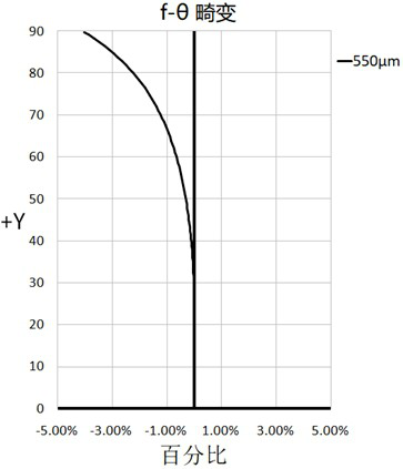
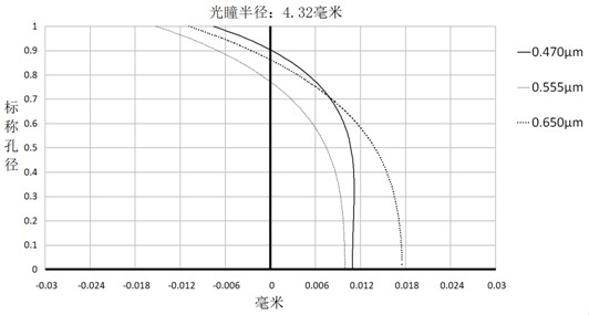
[0116] In this embodiment, the f-θ distortion, axial chromatic aberration, and vertical axis chromatic aberration diagrams of the super wide-angle lens 200 are as follows Image 6 , Figure 7 and Figure 8 shown.

[0117] Depend on Image 6 It can be seen that the optical distorti...

no. 3 example

[0121] see Figure 9 , is a schematic diagram of the structure of the ultra-wide-angle lens 300 provided in the third embodiment of the present invention. The structure diagram of the ultra-wide-angle lens 300 provided in the third embodiment is roughly the same as that of the ultra-wide-angle lens 100 in the first embodiment, except that: this embodiment The ultra-wide-angle lens 300 in the example adds a protective glass G2 between the filter G1 and the imaging surface S16. The protective glass G2 can better protect the sensor chip and present better imaging quality; in addition, the curvature radius and thickness of each lens etc. are also different, and the relevant parameters of each lens are shown in Table 5.

[0122] table 5

[0123]

[0124] Table 6 shows the aspherical parameters of the seventh lens L7 in this embodiment.

[0125] Table 6

[0126]

[0127] In this embodiment, the distortion, axial chromatic aberration, and vertical axis chromatic aberration d...


PUM


Abstract

The invention discloses an ultra-wide-angle lens and imaging equipment, and the ultra-wide-angle lens sequentially comprises,from an object side to an imaging surface along an optical axis, a first lens with negative focal power, wherein the object side surface of the first lens is a convex surface, and the image side surface of the first lens is a concave surface; a second lens with negative focal power, wherein the object side surface and the image side surface of the second lens are concave surfaces; a third lens with positive focal power, wherein the object side surface and the image side surface of the third lens are convex surfaces; a fourth lens with positive focal power, wherein the object side surface and the image side surface of the fourth lens are convex surfaces; a diaphragm; a fifth lens with positive focal power, wherein the object side surface and the image side surface of the fifth lens are convex surfaces; a sixth lens with negative focal power, wherein the object side surface and the image side surface of the sixth lens are concave surfaces, and the fifth lens and the sixth lens form a bonding body; and a seventh lens with positive focal power, wherein the object side surface and the image side surface of the seventh lens are convex surfaces near the axis. The ultra-wide-angle lens has the advantages of ultra wide angle, small temperature drift, low chromatic aberration and high resolution.

Description

technical field [0001] The invention relates to the technical field of imaging lenses, in particular to an ultra-wide-angle lens and imaging equipment. Background technique [0002] With the continuous improvement of people's demand for driving safety and the continuous maturity of ADAS (Advanced Driver Assistance System) technology, the market demand for vehicle cameras is growing explosively. Through the front-view, rear-view, surround-view and other vehicle-mounted lenses on the vehicle, it is possible to obtain all-round information inside and outside the vehicle, thereby helping the driver to make correct driving behaviors. Safety guarantee during driving. [0003] Due to the complex and changeable application environment of automobiles and high safety performance requirements, higher requirements are put forward for the automotive lenses installed in ADAS. To ensure that the lens can maintain good resolution in high and low temperature environments; it also needs to ...

Claims


Application Information

Patent Timeline
IPC IPC(8): G02B13/06G02B13/00G02B13/18
CPCG02B13/06G02B13/0045G02B13/18
Inventor 鲍宇旻梁流峰曾吉勇
Owner 合肥联创光学有限公司
Why Eureka
Try Eureka