
Deposition and milling integrated double-station 3D printer

A 3D printer and 3D printing technology, used in manufacturing tools, milling machine equipment, additive processing, etc., can solve problems such as inconcentration of energy, lengthy motion control codes, splashing of molten metal droplets, etc.

Active Publication Date: 2021-07-06
赵晴堂
View PDF11 Cites 1 Cited by
  • Summary
  • Abstract
  • Description
  • Claims
  • Application Information

AI Technical Summary

Problems solved by technology

[0004] 1. Insufficient interlayer fusion caused by uneven energy distribution, non-concentrated energy, unstable energy supply, and uncertain factors in the energy conversion process;
[0005] 2. Uneven energy distribution (point discharge), resulting in pores in the formed tissue;
[0006] 3. Factors such as uneven energy distribution and metal heat conduction lead to internal stress in the structure, which eventually leads to interlaminar cracks in the formed structure;
[0007] 4. Energy distribution is uneven, energy is not concentrated, energy supply is unstable, and there is a hump problem in the formed weld bead
[0008] 2. Especially in the 3D printing technology using metal wire materials, there is still the uneven flow of molten metal due to the problem of surface tension of the molten metal, which can also cause humps and uneven thickness, resulting in forming failure
[0009] 3. During the forming process, due to the mechanical force generated during the arc heating process, the molten metal droplets are splashed
[0010] The general solution is to use a multi-axis numerical control system to simulate the cranking process in manual TIG welding by swinging the welding torch regularly along the forming path during the 3D forming process. Although this can solve part of the problem, it will lead to programming difficulties , motion control code lengthy, mechanical structure is too complex and other new problems
[0011] 4. The forming precision is not high, and the layer pattern is serious

Method used


Image

  • Deposition and milling integrated double-station 3D printer
  • Deposition and milling integrated double-station 3D printer
  • Deposition and milling integrated double-station 3D printer

Examples


Embodiment Construction

[0096] In order to make the technical means, creative features, goals and effects of the present invention easy to understand, the present invention will be further elaborated below in conjunction with specific illustrations.

[0097] In order to make the purpose, features and advantages of the present invention more obvious and understandable, the technical solutions in the embodiments of the present invention will be clearly and completely described below in conjunction with the accompanying drawings in the embodiments of the present invention. Obviously, the following The described embodiments are only some, but not all, embodiments of the present invention. Based on the embodiments of the present invention, all other embodiments obtained by persons of ordinary skill in the art without making creative efforts belong to the protection scope of the present invention.

[0098] In the description of the present invention, it should be understood that the orientations or positio...


PUM


Abstract

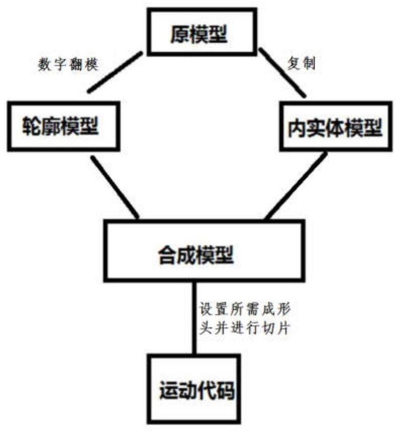
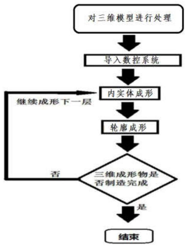
The invention discloses a deposition and milling integrated double-station 3D printer. According to the deposition and milling integrated double-station 3D printer, firstly, a three-dimensional formed object to be printed is subjected to model treatment; in the treatment process, the forming process of the three-dimensional formed object is divided into two parts which are related in shape and different in function to conduct forming according to different principles; and according to the operation of dividing forming of the three-dimensional formed object into two parts which are related in shape and different in function to conduct forming according to different principles, a three-dimensional model is divided into an inner solid model, an inner contour model and an outer contour model, the inner solid model is subjected to additive forming through a fused deposition nozzle, the inner contour model and the outer contour model are subjected to subtractive forming through a milling module, and the fused deposition nozzle and the milling module are mounted on a multi-station lifting type switching tackle.

Description

technical field [0001] The invention relates to a 3D printing technology, in particular to a deposition-milling integrated double-station 3D printer. Background technique [0002] There are many defects and problems in the 3D printing technology of metal materials that use arc or plasma as the heat source for heating and melting, including: [0003] 1. Due to the uneven energy distribution, energy inconcentration, and unstable energy supply of the arc or plasma, various complex defects include: [0004] 1. Insufficient interlayer fusion caused by uneven energy distribution, non-concentrated energy, unstable energy supply, and uncertain factors in the energy conversion process; [0005] 2. Uneven energy distribution (point discharge), resulting in pores in the formed tissue; [0006] 3. Factors such as uneven energy distribution and metal heat conduction lead to internal stress in the structure, which eventually leads to interlaminar cracks in the formed structure; [0007...

Claims


Application Information

Patent Timeline
IPC IPC(8): B22F3/115B23C3/00B33Y10/00B33Y30/00B33Y50/02
CPCB33Y10/00B33Y30/00B33Y50/02B22F10/22B22F10/85B22F12/53B22F12/82B22F12/13Y02P10/25
Inventor 赵晴堂
Owner 赵晴堂
Learn More