
A kind of robot end effector and robot

An end effector and robot technology, applied in the field of grinding and processing, can solve the problems of poor processing quality stability, large surface roughness, and unsatisfactory surface quality of the workpiece, so as to improve processing accuracy and quality, and improve processing efficiency and precision , The effect of increasing the applicable range of processing

Active Publication Date: 2022-06-28
SHANGHAI AIRCRAFT MFG
View PDF6 Cites 0 Cited by
  • Summary
  • Abstract
  • Description
  • Claims
  • Application Information

AI Technical Summary

Problems solved by technology

At present, hand-held pneumatic grinders are commonly used in the aircraft manufacturing process, which completely rely on human experience to control the grinding force, angle, and time. There are problems such as poor processing quality stability and low efficiency. A large amount of dust in the process will cause great harm to the health of operators
[0003] Among the existing automatic grinding devices, such as the rotary processing end effector without axial vibration, for the processing of hard and brittle materials such as carbon fiber composite materials, since a large cutting force is required for cutting, the workpiece will be relatively heavy during the processing. Large surface roughness, etc., the surface quality of the workpiece is not ideal; for the robot flexible grinding system, by installing a force sensor in front of the grinding tool, the processing pressure is captured, and the end position of the mechanical arm is adjusted according to the pressure to achieve flexible processing. However, the feedback The control system has a certain delay, and the effect of this flexible control strategy to maintain a constant pressure is not ideal; for the ultrasonic grinding device, by installing an ultrasonic vibrator between the motor and the processing tool, the rotational vibration processing of the processing tool is realized. However, the device is large in size and complex in structure, so it is not suitable to be installed on the robot

Method used


Image

  • A kind of robot end effector and robot
  • A kind of robot end effector and robot
  • A kind of robot end effector and robot

Examples


Embodiment Construction

[0042] In order to make the technical problems solved by the present invention, the technical solutions adopted and the technical effects achieved more clearly, the technical solutions of the embodiments of the present invention will be described in further detail below with reference to the accompanying drawings. Obviously, the described embodiments are only the present invention. Some examples, but not all examples. Based on the embodiments of the present invention, all other embodiments obtained by those skilled in the art without creative efforts shall fall within the protection scope of the present invention.

[0043] In the description of the present invention, unless otherwise expressly specified and limited, the terms "connected", "connected" and "fixed" should be understood in a broad sense, for example, it may be a fixed connection, a detachable connection, or an integrated ; It can be a mechanical connection or an electrical connection; it can be a direct connection...


PUM


Abstract

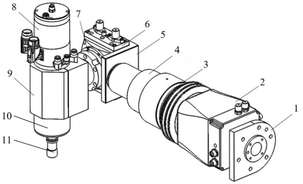
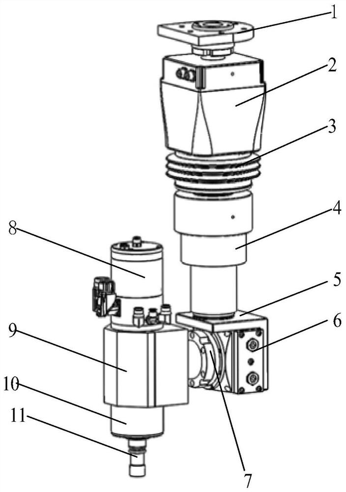
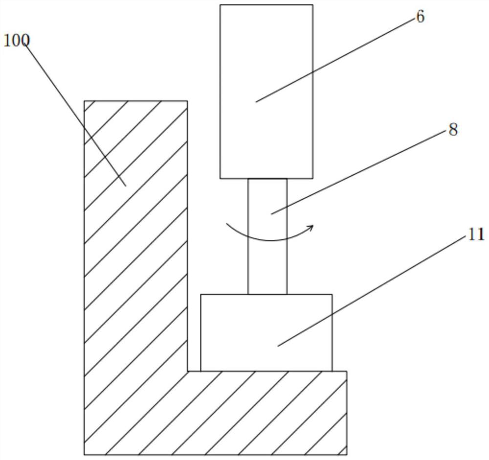
The invention discloses a robot end effector and a robot, belonging to the technical field of grinding and processing. The end effector of the robot is used for grinding and processing the workpiece, including the execution tool, the rotary unit, the rotation unit, the ultrasonic vibrator and the constant force control component, wherein, one end of the rotary unit is connected with the execution tool, and the rotary unit is used to drive the execution tool to rotate Movement; the rotary unit is used to drive the rotary unit to perform rotary motion, and the direction of the rotary motion is not in the same direction as the rotary motion direction; the ultrasonic vibrator is connected to the rotary unit, and the ultrasonic vibrator is used to drive the rotary unit and the execution tool to vibrate axially; constant force control components Used to maintain a constant contact pressure between the implement and the workpiece. A robot includes the above-mentioned robot end effector. The robot end effector provided by the invention simplifies the structure, reduces the difficulty of control, and improves the processing quality and work efficiency through structural design and constant contact pressure control.

Description

technical field [0001] The invention relates to the technical field of grinding and processing, in particular to a robot end effector and a robot. Background technique [0002] At present, the overall processing of the aircraft body and large parts is the most important and most difficult process in the coating process for civil aircraft manufacturers and maintenance plants. The defects generated by processing will directly reflect the final appearance. The surface finish quality largely determines the final paint quality and effect of the aircraft. At present, hand-held pneumatic grinding machines are generally used in the aircraft manufacturing process, which completely relies on human experience to control the grinding force, angle, and time. There are problems such as poor processing quality stability and low efficiency, especially when processing composite materials. The reliability of the fuselage is difficult to guarantee, and the processing A large amount of dust in...

Claims


Application Information

Patent Timeline
Patent Type & Authority Patents(China)
IPC IPC(8): B24B1/04B24B47/12B24B51/00B25J11/00
CPCB24B1/04B24B47/12B24B51/00B25J11/0065
Inventor 易俊兰邱太文宋袁曾毛景李亚萍富双超
Owner SHANGHAI AIRCRAFT MFG
Learn More