Efficient waste gas treatment system and process

A waste gas treatment, high-efficiency technology, applied in the direction of gas treatment, dispersed particle separation, membrane technology, etc., can solve the problems of PM2. The effect of catalytic activity

Active Publication Date: 2021-07-09
江苏舒源空调制造有限公司
View PDF22 Cites 1 Cited by
  • Summary
  • Abstract
  • Description
  • Claims
  • Application Information

AI Technical Summary

Problems solved by technology

The composition of industrial waste gas is complex and diverse, and waste gas containing gaseous pollutants such as VOC, odor, sulfur oxides, nitrogen oxides or dioxins is particularly difficult to treat. The current treatment methods mostly use liquid washing or activated carbon for adsorption, liquid washing Including water washing, alkali washing, pickling, etc. During the liquid washing process, there are problems such as the exhaust gas and the liquid cannot be completely contacted or the contact time is short. The exhaust gas that has not fully contacted with the washing liquid still contains a large amount of harmful substances, causing the discharge to fail to meet the standards.
After the activated carbon adsorption method is saturated, activated carbon desorption is required, which will easily cause activated carbon wear and generate PM2.5 dust pollution, and after the service life of activated carbon is reached, the used activated carbon is a hazardous waste, which needs to be processed by a special hazardous waste treatment agency, and the cost of use high

Method used


Image

  • Efficient waste gas treatment system and process
  • Efficient waste gas treatment system and process

Examples


Embodiment Construction

[0022] The present invention will be further described below in conjunction with the accompanying drawings and specific embodiments.

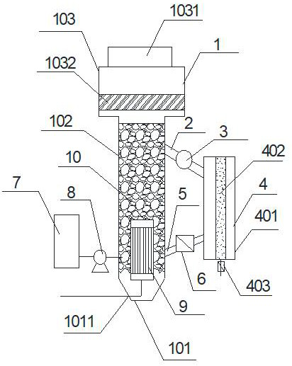
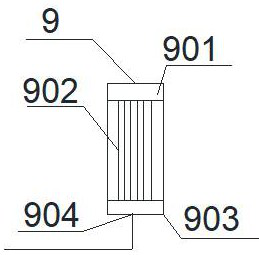
[0023] like figure 1 As shown, a high-efficiency waste gas treatment system includes a slurry bed 1, an overflow pipe 2, an overflow pump 3, a liquid-solid separator 4, a return pipe 5, a return valve 6, a chemical storage tank 7, a chemical dosing pump 8, Exhaust gas distributor 9, molecular sieve 10, said slurry bed 1 and liquid-solid separator 4 are equipped with heating and heat preservation devices outside; said slurry bed 1 includes lower bed body 101, middle bed body 102, expansion section 103, said One end of the overflow pipe 2 is connected to the upper part of the middle bed body 102, and the other end is connected to the upper part of the liquid-solid separator 4. A gas outlet 1031 is opened on the top of the enlarged section 103, and a mist eliminator 1032 is installed inside. One of net demister, particle packing demister or wet e...


PUM


Abstract

The invention provides an efficient waste gas treatment system and process, the efficient waste gas treatment system comprises a slurry bed, an overflow pipe, an overflow pump, a liquid-solid separator, a return pipe, a return valve, a medicament storage tank, a dosing pump, a waste gas distributor and a molecular sieve; wherein the slurry bed comprises a lower bed body, a middle bed body and an expansion section, one end of the overflow pipe is connected with the upper part of the middle bed body, and the other end of the overflow pipe is connected with the upper part of the liquid-solid separator; one end of the return pipe is connected with the lower part of the liquid-solid separator, the other end of the return pipe is connected with the lower part of the middle bed body, the return valve is positioned on the return pipe, the inlet end of the dosing pump is connected with the medicament storage tank, and the outlet end of the dosing pump is connected with the middle bed body; the waste gas distributor is positioned in the middle bed body and comprises an upper seal head, a perforated pipe, a lower seal head and a gas inlet, wherein the perforated pipe is located between the upper sealing head and the lower sealing head, and the slurry bed is filled with the molecular sieve. According to the efficient waste gas treatment process, the waste gas can be in full contact with the treatment agent, gaseous pollutants in the waste gas can be efficiently removed without generation of secondary pollutants such as PM2.5.

Description

technical field [0001] The invention belongs to the technical field of waste gas treatment, and in particular relates to an efficient waste gas treatment system and process. Background technique [0002] With the strengthening of environmental protection, people pay more and more attention to waste gas treatment. The composition of industrial waste gas is complex and diverse, and waste gas containing gaseous pollutants such as VOC, odor, sulfur oxides, nitrogen oxides or dioxins is particularly difficult to treat. The current treatment methods mostly use liquid washing or activated carbon for adsorption, liquid washing Including water washing, alkali washing, pickling, etc., there are problems in the liquid washing process that the exhaust gas and the liquid cannot be completely contacted or the contact time is short. The exhaust gas that has not fully contacted with the washing liquid still contains a large amount of harmful substances, causing the discharge to fail to meet...

Claims


Application Information

Patent Timeline
Patent Type & Authority Applications(China)
IPC IPC(8): B01D53/78B01D53/60B01D53/44B01D53/86
CPCB01D53/44B01D53/78B01D53/86B01D53/8637B01D53/8671B01D2257/708
Inventor 许铭勋
Owner 江苏舒源空调制造有限公司
Why Eureka
Try Eureka