Soil disinfection and soil remediation combined method and device
A soil remediation and soil disinfection technology, which is applied in the field of soil governance, can solve the problems of increased stoppage time in shed areas, uncontrollable drug volatilization, and difficulty in inhibiting crop growth, etc., to reduce the stoppage time, prevent inhibition of crop growth, Effect of reducing difficulty of weeding
- Summary
- Abstract
- Description
- Claims
- Application Information
AI Technical Summary
Problems solved by technology
Method used
Image
Examples
Embodiment 1
[0034] A combined method for soil disinfection and soil restoration, comprising the following steps;
[0035] Step 1: Clear the shed, remove the crop straws, crop residues, sprinkler irrigation pipes, vine auxiliary growth frames and other sundries in the shed area on the surface of the shed area, and take samples of the soil in the shed area to detect the types of pathogens in the soil and pH, and determine the type and amount of application according to the test results;
[0036] Step 2: Flood irrigation, build a cofferdam on the surface, and use flood irrigation to irrigate the land to maintain a suitable temperature in the shed area, so that the weeds in the soil can germinate, and after the grass seeds germinate, ventilate and dry the land. The land after flood irrigation can Promote the germination of weeds and weeds, improve the pH of the soil, and increase the activity of pathogens in the soil with appropriate temperature and humidity, which is conducive to subsequent ...
Embodiment 2
[0042] Embodiment 2: the difference based on Embodiment 1 is;
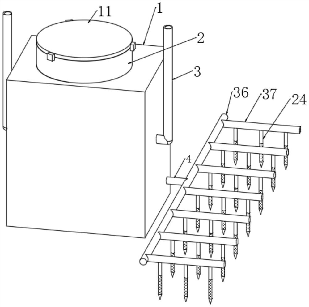
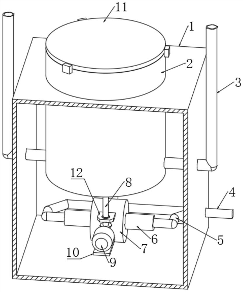
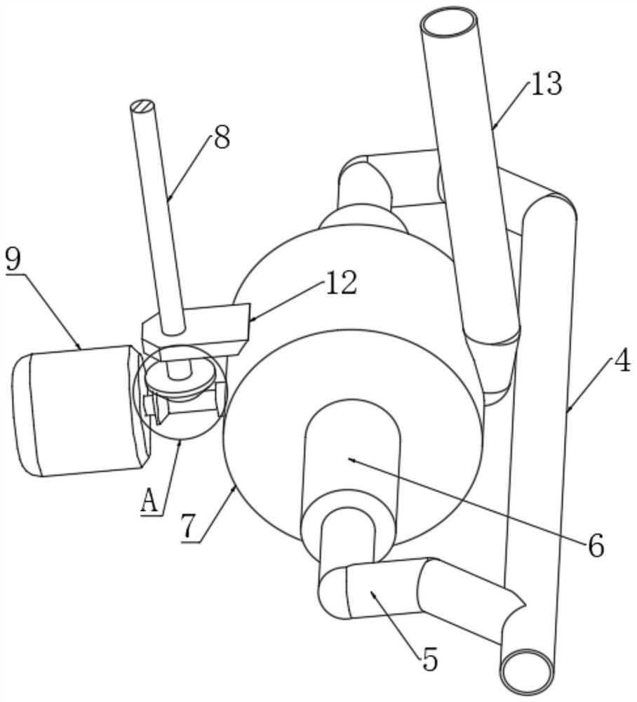
[0043] refer to Figure 1-7 , the present invention also provides a combined device for soil disinfection and soil remediation in the combined method, comprising a box body 1 and a tank body 2, the upper end of the box body 1 is fixedly connected with the side wall of the tank body 2 through a circular opening, The upper end of the tank body 2 is provided with an opening and the opening is connected with a sealing plate 11 through a lock, the inner wall of the lower end of the tank body 2 is fixedly connected with an air intake pipe 13, and the lower end of the air intake pipe 13 runs through the side wall of the tank body 2 and is fixedly connected with a shell body 7, and the shell 7 is a cylindrical structure, the shell 7 is connected with a pressurizing mechanism, both sides of the shell 7 are fixedly connected with the sleeve 6, and the opposite ends of the two sleeves 6 are fixedly connected with a feeder T...
Embodiment 3
[0045] Embodiment 3: the difference based on embodiment 2 is;
[0046] refer to Figure 4-5 , the pressurizing mechanism comprises two guide rods 25, and the two guide rods 25 are fixedly connected with the inner wall of the housing 7, and the housing 7 is provided with a rectangular frame 14, and the side wall of the rectangular frame 14 is connected to the guide rod 25 through the guide hole. The bar wall is slidingly socketed, and the opposite sides of the rectangular frame 14 are fixedly connected with a cross bar 22, and the ends of the two cross bars 22 away from the rectangular frame 14 respectively extend into the two sleeves 6, and the sleeves 6 are slidingly sleeved with Piston 15, and one side center of piston 15 is fixedly connected with one end of cross bar 22, is provided with sliding sleeve 28 in air supply pipe 5, and the side wall of sliding sleeve 28 is fixedly connected with two connecting blocks 20, and connecting block 20 One end of one end is fixedly con...
PUM
 Abstract
Description
Claims
Application Information
 - R&D
- Intellectual Property
- Life Sciences
- Materials
- Tech Scout
- Unparalleled Data Quality
- Higher Quality Content
- 60% Fewer Hallucinations
Browse by: Latest US Patents, China's latest patents, Technical Efficacy Thesaurus, Application Domain, Technology Topic, Popular Technical Reports.
© 2025 PatSnap. All rights reserved.Legal|Privacy policy|Modern Slavery Act Transparency Statement|Sitemap|About US| Contact US: help@patsnap.com


