Laser double-beam welding tool for outer side of aircraft panel

A technology for welding tooling and aircraft siding, applied to laser welding equipment, welding equipment, welding equipment, etc., can solve problems such as reduced production efficiency, skin damage, and improper assembly, so as to improve welding efficiency, increase pass rate, The effect of convenient welding

Pending Publication Date: 2021-07-09
CHENGDU HONGXIA TECH CO LTD
View PDF0 Cites 3 Cited by
  • Summary
  • Abstract
  • Description
  • Claims
  • Application Information

AI Technical Summary

Problems solved by technology

[0004] In the process of connecting the long truss to the wing skin, laser welding is generally used, and the laser welding device is usually operated manually, and the products to be welded are also positioned manually. During the positioning process, the supports, beams and clips The assembly between the plates is not in place, and the precise docking of the girders and skins of different

Method used


Image

  • Laser double-beam welding tool for outer side of aircraft panel
  • Laser double-beam welding tool for outer side of aircraft panel
  • Laser double-beam welding tool for outer side of aircraft panel

Examples


Embodiment 1

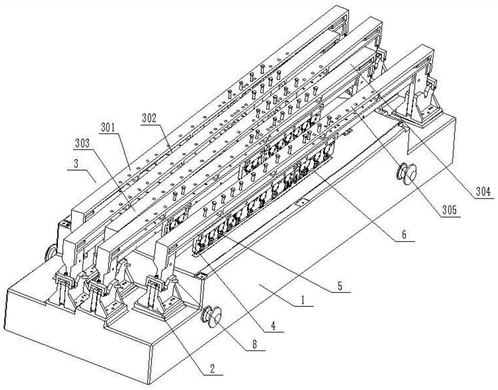
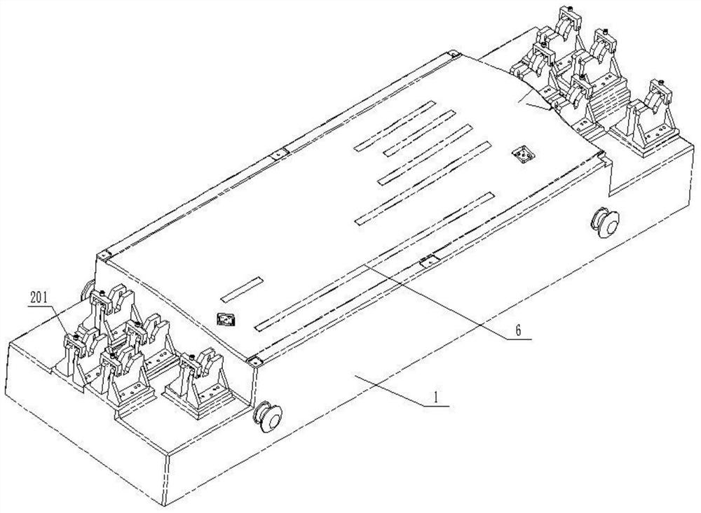
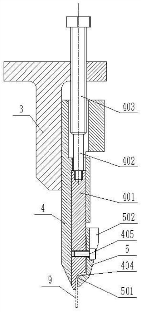
[0038] A laser double-beam welding tool for the outer side of an aircraft wall panel, such as Figure 1-Figure 9 As shown, it includes a base 1 and a support 2 provided at both ends of the base 1. At least one crossbeam 3 is fixed on the support 2, and each crossbeam 3 is provided with at least one set of clamping plates 4, and each set of clamping plates 4 is fixed There are a plurality of pressing plates 5 evenly arranged; the matching of the clamping plates 4 and the pressing plates 5 stipulates the workpiece on the beam 3, and the base 1 is provided with at least one set of copper sheets 6 for carrying the skin. The sheet 6 corresponds to the workpiece on the pallet 4, the bottom of the copper sheet 6 is provided with a pressure sensor 7; the beam 3 and the support 2 are provided with a position sensor, and the position sensor on the support 2 is used to detect The positional relationship between the crossbeam 3 and the support 2 , the position sensor on the crossbeam 3 is...

Embodiment 2

[0049] Take the outer tooling of the upper left wall panel as an example, such as Figure 1-Figure 9 shown;

[0050] The laser double-beam welding tooling of the present invention includes 5 sets of supports 2, each set of 2 supports 2, and each set of supports 2 is equipped with a crossbeam 3, that is, No. 1 crossbeam 301, No. 2 crossbeam 302, No. 3 crossbeam Beam 303 , Beam No. 4 304 and Beam No. 5 305 .

[0051] Among them, No. 1 crossbeam 301 is fixed with a group of clamping plates 4, and No. 1 long stringer is fixed on the clamping plates 4;

[0052] There is a long stringer positioned on the No. 2 beam, that is, the No. 2 stringer;

[0053] There is a long stringer positioned on the No. 3 beam, that is, the No. 3 stringer;

[0054] There are three girders positioned on No. 4 beam, namely, No. 4 girder, No. 5 girder, and No. 6 girder;

[0055] There are two girders positioned on No. 5 beam, namely, No. 7 girder and No. 8 girder;

[0056] Each girder corresponds to a...


PUM


Abstract

The invention discloses a laser double-beam welding tool for the outer side of an aircraft panel, and belongs to the laser welding technology. The welding tool comprises a base and a support, cross beams are fixed to the support, each cross beam is provided with a clamping plate, and a plurality of pressing plates which are evenly arranged are fixed to each set of the clamping plates. The base is provided with at least one group of copper sheets for bearing stressed skin, and the bottom of each copper sheet is provided with a pressure sensor. Position sensors are arranged on the cross beams and the support, the position sensors on the support are used for detecting the position relation between the cross beams and the support, and the position sensors on the cross beams are used for detecting the position relation between the cross beams and the clamping plates. The position corresponding relation of the cross beams and the support and the clamping plates can be determined through position induction, the welding efficiency of a stringer and the stressed skin is improved, the pressure sensors are arranged below the copper sheets, the pressure applied to the stressed skin by pressing tongues on the clamping plates can be detected, damage to the stressed skin due to the fact that the applied pressure is too large is effectively prevented, and the product percent of pass is improved.

Description

technical field [0001] The invention relates to laser welding technology, in particular to a laser double-beam welding tool for the outer side of an aircraft wall plate. Background technique [0002] The principle of laser welding can be divided into heat conduction welding and laser deep penetration welding. The principle of heat conduction laser welding is that laser radiation heats the surface to be processed, and the surface heat diffuses to the inside through heat conduction. By controlling the width, energy, peak power and repetition of laser pulses Frequency and other laser parameters can melt the workpiece and form a specific molten pool. [0003] Modern aircraft generally have a complex double-curvature aerodynamic shape, and there are a large number of parts whose shape changes with the curvature of the shape, among which the long stringer is the most typical. The wing stringers of the aircraft are closely attached to the inner surface of the wing skin and distrib...

Claims


Application Information

Patent Timeline
IPC IPC(8): B23K26/70B23K26/21B23K37/04
CPCB23K37/0443B23K26/21B23K26/702
Inventor 朱荣文李春俊李毅吴胜忠游波
Owner CHENGDU HONGXIA TECH CO LTD
Why Eureka
Try Eureka