Wafer bar end cutting device

A wafer and end-cutting technology, applied in the direction of fine working devices, working accessories, manufacturing tools, etc., can solve the problems of high work intensity of operators, low automation of wafer bar processing, and low efficiency of bar processing

Active Publication Date: 2021-08-20
四川上特科技有限公司
View PDF8 Cites 0 Cited by
  • Summary
  • Abstract
  • Description
  • Claims
  • Application Information

AI Technical Summary

Problems solved by technology

[0007] The existing device transfers the bar to the cutting device by manual handling when cutting both ends of the bar, and then cuts the end through the cutting device. After the cutting is completed, the bar is transferred to the corresponding coarse grinding device. Carry out rough grinding of the outer wall of the bar. This operation method has a low degree of automation in wafer bar processing, and the operator's work intensity is high, and the processing efficiency of the bar is low.

Method used


Image

  • Wafer bar end cutting device
  • Wafer bar end cutting device
  • Wafer bar end cutting device

Examples


Embodiment Construction

[0060] In order to make the purpose, technical solutions and advantages of the embodiments of the present invention clearer, the technical solutions in the embodiments of the present invention will be clearly and completely described below in conjunction with the drawings in the embodiments of the present invention. Obviously, the described embodiments It is a part of embodiments of the present invention, but not all embodiments. The components of the embodiments of the invention generally described and illustrated in the figures herein may be arranged and designed in a variety of different configurations.

[0061] Accordingly, the following detailed description of the embodiments of the invention provided in the accompanying drawings is not intended to limit the scope of the claimed invention, but merely represents selected embodiments of the invention. Based on the embodiments of the present invention, all other embodiments obtained by persons of ordinary skill in the art wi...


PUM


Abstract

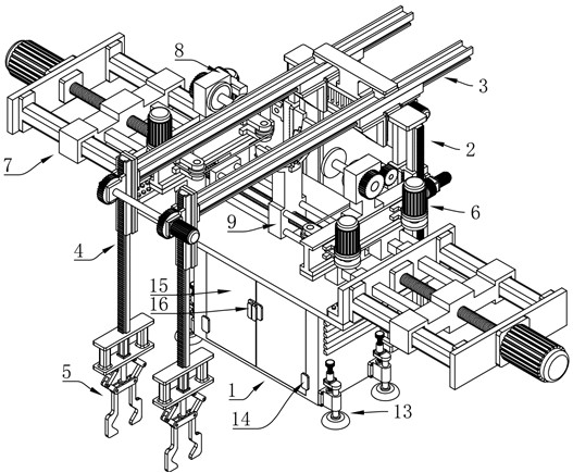
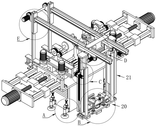
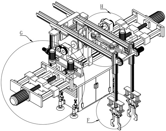
A wafer bar end cutting device, comprising: a support assembly, a first lifting assembly, a rear pulling mechanism, a second lifting mechanism, a clamping mechanism, an adjusting mechanism, an end cutting mechanism, a rotating mechanism and a rounding mechanism. The invention facilitates the automatic transfer of the wafer rod when processing the wafer rod, and can stably clamp the wafer rod when the wafer rod is transferred, thereby improving the safety of the wafer rod transfer , it is convenient to carry out the end cutting operation of the wafer bar, and at the same time, it can roughly grind the outer wall of the wafer plate. Through this device, the processing efficiency of the wafer bar can be significantly improved, and the working intensity of the operator can be reduced. It has a strong practicality.

Description

technical field [0001] The invention relates to the related technical field of wafer processing equipment, in particular to a wafer bar end cutting device. Background technique [0002] A chip is a general term for semiconductor component products. In electronics, it is a way to miniaturize circuits and is often manufactured on the surface of a semiconductor wafer. [0003] Wafer refers to the silicon wafer used to make silicon semiconductor circuits, and its raw material is silicon. High-purity polycrystalline silicon is dissolved and mixed with silicon crystal seeds, and then slowly pulled out to form cylindrical single crystal silicon. After the silicon ingot is ground, polished, and sliced, it forms a silicon wafer, that is, a wafer. [0004] The main processing methods of wafers are sheet processing and batch processing, that is, one or more wafers are processed at the same time. As semiconductor feature sizes become smaller and processing and measurement equipment b...

Claims


Application Information

Patent Timeline
Patent Type & Authority Patents(China)
IPC IPC(8): B28D5/04B28D7/00B28D7/04B24B5/04B24B5/50B24B41/06
CPCB24B5/047B24B5/50B24B41/067B28D5/0058B28D5/0082B28D5/045
Inventor 李健儿冯永张正胡仲波鲜贵容
Owner 四川上特科技有限公司
Why Eureka
Try Eureka