Integrated structure of brake and hub motor

An in-wheel motor and brake technology, applied in the field of electric wheels, can solve the problems of poor brake matching, high production cost, difficult assembly, etc., and achieve the effects of reliable braking action, light equipment weight, and reduced vehicle cost.

Pending Publication Date: 2021-07-09
ZHEJIANG VIE SCI & TECH
View PDF1 Cites 0 Cited by
  • Summary
  • Abstract
  • Description
  • Claims
  • Application Information

AI Technical Summary

Problems solved by technology

[0005] The invention provides an integrated structure of the brake and the hub motor in view of the disadvantages of the existing wheel hub motors, such as assembly difficulties, high production costs, and poor matching with the brake.

Method used


Image

  • Integrated structure of brake and hub motor
  • Integrated structure of brake and hub motor
  • Integrated structure of brake and hub motor

Examples


Embodiment 1

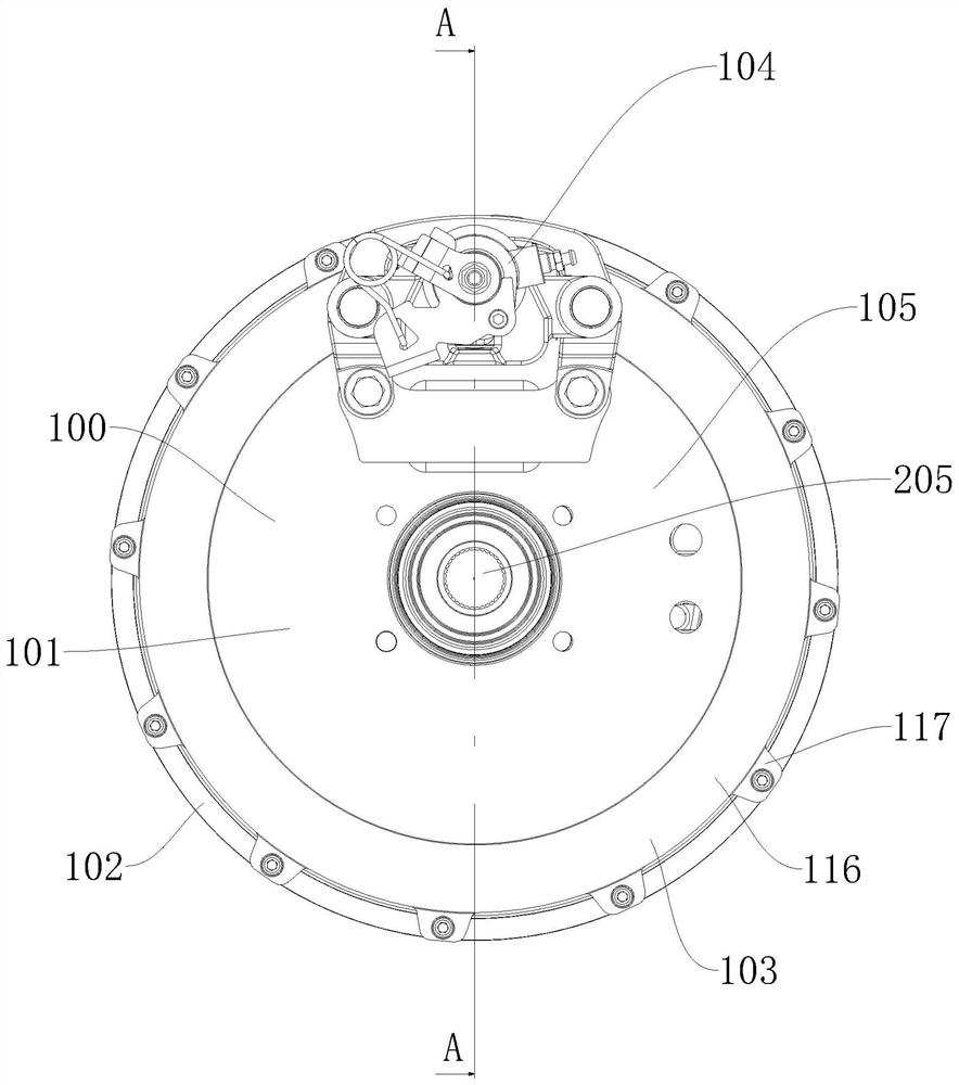
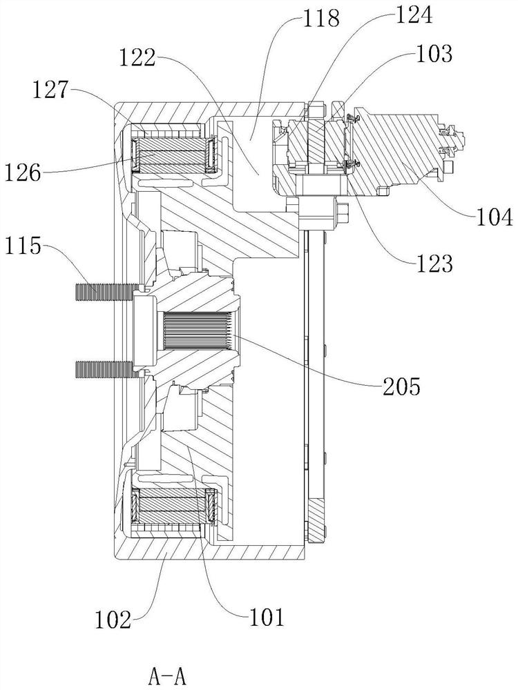
[0033] like Figure 1 to Figure 6 as well as Figure 10 As shown, the integrated structure of the brake and the hub motor includes a hub motor 100 and a brake 104. The hub motor 100 includes a stator 101 and a rotor 102 that drives the wheel to rotate. A brake disc 103 is installed on the rotor 102, and the brake 104 is installed on the stator 101. , the brake 104 can act on the brake disc 103 to realize the braking action. The end surface of one end of the stator 101 is the installation surface 105 , and in this embodiment, the installation surface 105 is the end surface of the end surface of the stator 101 close to the vehicle body when the in-wheel motor 100 is installed. The brake 104 and the steering knuckle 200 are installed on the mounting surface 105 , the brake disc 103 passes through the jaw 125 of the brake 104 , and the brake 104 can act on the brake disc 103 . In this embodiment, the driving bearing 115 is not a driving bearing, and the brake 104 can be selected...

Embodiment 2

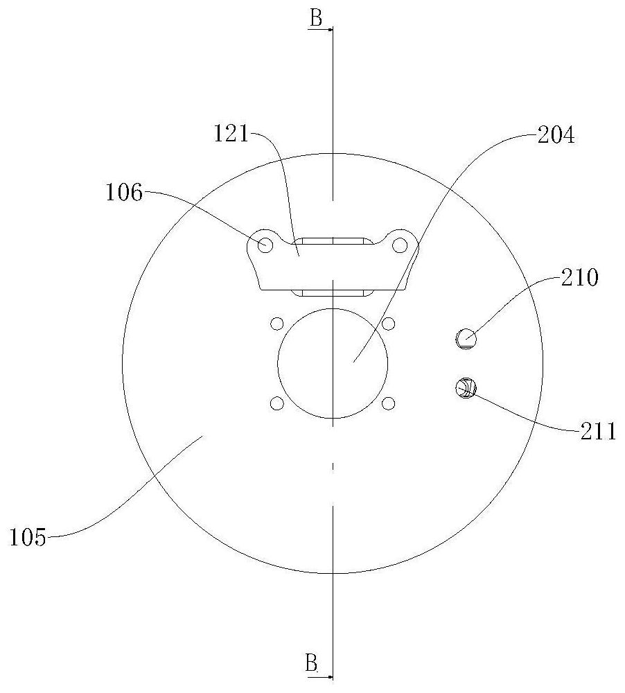
[0047] like Figure 7 to Figure 9 As shown, the difference from Embodiment 1 is that in order to simplify the manufacturing difficulty of the stator 101, the mounting seat 121 and the stator 101 are detachable structures. In this case, the mounting seat 121 can be selected according to actual needs. Heat treatment or other processes enable the mounting seat 121 to meet the installation requirements, and the stator 101 with this structure has lower production cost and is universal. In this embodiment, the mounting base 121 is provided with a second mounting hole 107, and the connector of the mounting base 121 passes through the second mounting hole 107 to fix the mounting base 121 on the stator 101, and the stator 101 is provided with a second mounting hole. 107 is matched with the third mounting hole 108, and the caliper body of the brake 104 is fixed with a mounting ear 109, and the mounting ear 109 is fixedly mounted on the first connecting hole on the mounting base 121 thro...

Embodiment 3

[0051] The difference between this embodiment and Embodiment 1 and Embodiment 2 is that the brake 104 in this embodiment is a multi-piston fixed brake 104, and the fixed brake 104 can provide stable and reliable braking force. The fixed brake 104 is structurally designed. The brake 104 includes a brake caliper body. The brake caliper body includes an upper caliper body 123 and a lower caliper body 124. An arc bayonet 125 is formed between the upper caliper body 123 and the lower caliper body 124. The brake disc 103 is installed in the arc bayonet 125, the brake disc 103 passes through the arc bayonet 125, the shape of the arc bayonet 125 matches the shape of the brake disc 103, the upper caliper body 123 and the lower caliper body 124 is a detachable structure, which is convenient for processing. The upper clamp body 123 and the lower clamp body 124 are fixedly connected by fixing bolts. The number of fixing bolts is not less than two, and this design avoids the traditional fix...


PUM


Abstract

The invention relates to the field of power wheels, and discloses an integrated structure of a brake and a hub motor, which comprises a hub motor and a brake, the hub motor comprises a stator and a rotor for driving a wheel to rotate, a brake disc is mounted on the rotor, the brake is mounted on the stator, and the brake can act on the brake disc to realize a braking action. The hub motor is an outer rotor motor, the brake disc is annular and installed on the outer end face of the stator, the stator is arranged on the inner side of the rotor, and the brake is installed on the outer end face of the stator and located on the inner side of the brake disc. The integrated design of the hub motor and the brake is creatively adopted, the assembling procedures and the assembling cost of the electric wheel are greatly reduced, and the braking action can be stably and reliably performed through the integrated design. And meanwhile, the brake and the hub motor are integrally designed, so that the space in the electric wheel and the rim is greatly saved, and the integrated action of starting and braking can be realized without structural design of the rim.

Description

technical field [0001] The invention relates to the field of electric wheels, in particular to an integrated structure of a brake and a hub motor. Background technique [0002] In the design of existing hub motors, the hub motor is generally arranged in the rim, and then brake discs and brakes are installed on the vehicle body or wheels to realize the braking function. [0003] Chinese patent CN201710537261.0 provides a wheel hub motor with a column. The application of the invention provides cooling fins on the housing, and uses the outer end cover, side wall and inner end cover to form a cooling fluid circulation channel, which can greatly Improve the heat dissipation performance of the present invention; further, holes are processed in the iron core of the stator, and cooling pipelines are installed in the holes for passing the cooling liquid and taking away heat, thereby improving the reliability of the hub motor and improving the reliability of the hub motor. Environmen...

Claims


Application Information

Patent Timeline
Patent Type & Authority Applications(China)
IPC IPC(8): B60K7/00B60T1/06
CPCB60K7/0007B60T1/065
Inventor 陈锋马志敏耿传亮董胜男黄梅仙
Owner ZHEJIANG VIE SCI & TECH
Why Eureka
Try Eureka